Continue to Site

Welcome to EDAboard.com

Welcome to our site! EDAboard.com is an international Electronics Discussion Forum focused on EDA software, circuits, schematics, books, theory, papers, asic, pld, 8051, DSP, Network, RF, Analog Design, PCB, Service Manuals... and a whole lot more! To participate you need to register. Registration is free. Click here to register now.

Reverse current trough solar panel...

Status
Not open for further replies.

Externet

Advanced Member level 2
Joined
Jan 29, 2004
Messages
570
Helped
28
Reputation
58
Reaction score
29
Trophy points
1,308
Location
Mideast US
Activity points
5,563
Hi.
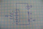
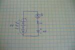
A Lithium cell fully charged at 4V, placed on a circuit as attached, with a (small) 5V solar panel with 10 cells, in darkness, without blocking diode.
What current to expect ?
Will the cell discharge only to the white LED Vf value ?
What Vr presents a solar panel ?
Will the LED shine ?
 

Attachments

  • P1010685.jpg
    P1010685.jpg
    160.9 KB · Views: 62

A better picture, attached.
 

Attachments

  • P1010686.jpg
    P1010686.jpg
    203.5 KB · Views: 58

The LED polarity is backwards for charging. The white LED uses about 3.3V so the battery gets only 5V - 3.3V= 1.7V and therefore will not charge. I don't know if the LED will light when it gets dark, usually a circuit detects low solar panel voltage then turns on the LED..
You must[/] use a battery charger IC designed for a lithium battery to avoid an explosion or a very hot fire.
 

Hi.
This is not about charging which is not possible trough the LED as connected, and not part of the question.
It is about the behavior of discharging the lithium cell trough the LED and solar panel.
 

Just now I connected the 2V solar panel from a solar garden light to a 9V battery, resistor and white LED as in your schematic. The LED did not light when the solar panel was in the dark or when it got lots of light.
The resistance of my solar panel in the dark is 1.2M but yours will be different. I did not measure the leakage current of the LED at a voltage less that when it is lit.
 

Thanks.
That is what I experienced. With a 3.77V Li, a 9 cell panel in the dark, 100 ohms, white LED. Nope. No light.

That made me wonder... If the typical blocking diode used in series with a panel is to prevent the associated battery from discharging through the panel when dark, why is not happening ?
No blocking diode as in the schematic and there is no current. Not even 1 mA.

But the blocking diode affair in series with a solar panel is very recommended in all literature I see. Again, not having it in the circuit showed no current. 8-O
Why ¿? :bang:

- - - Updated - - -

Been several hours testing the contraption circuit. Voltage still at 3.77V. Voltage across the 100 ohm resistor is 2.2mV which yields 0.02mA. Will leave overnight.

Just found this----> **broken link removed**

This is becoming ´the debunking of the blocking diode´. Abolish the blocking diode ? :-?
 

The 'ybw' link is written by people who do not understand electronics very well and I think they misunderstand what the diodes are for.

You must understand that diodes on PV panels are used in two ways: A blocking diode is wired in series with the panel and it's purpose is to prevent 'back flow' when it produces less voltage than present on its load. A bypass diode is wired across (in parallel) with the PV panel and it's purpose is to allow continued flow of current along a chain of two or more panels wired in series so one does not stop the power production of the other if it becomes shaded.

Your schematic shows an LED wired so it does nothing useful at all. It might light dimly if the PV is in darkness but it would only do so by leakage current in the PV panel which would be very small. If it is supposed to light up when the battery is charging from the PV, it is wired backwards but even then it would only light if the PV voltage was more than the battery voltage + Vf of the LED so it wouldn't be useful as a charge indicator.

A simplistic way of imagining PV modules is to think of them as diodes that produce Vf across themselves when insolated. Typically each diode will produce around 0.6V (count up the number wired in series in a panel and you will see it matches the panels voltage rating!) but when in darkness they behave more like ordinary silicon diodes.

To debunk the idea that the blocking diodes are not needed, consider this scenario: You have four 6V PV modules in series to make a total of 24V, they connect directly to a battery and it charges as expected in sunlight. Now look what happens in darkness, the battery is still 24V and it appears across the ends of the four PV modules. With a blocking diode no current will flow and everything is OK, without a blocking diode the voltage will be distributed across the panels but possibly (probably) not equally so one or more panel may suffer reverse voltage breakdown. Looking at my own system here, I have two grid tied arrays, one produces 96V maximum (~300W peak), the other produces around 210V (~1.5KW peak), without both diodes it would produce significantly less power and be very prone to PIV damage.

Brian.
 
  • Like
Reactions: burai

    burai

    Points: 2
    Helpful Answer Positive Rating
Your reverse voltage across the solar panel is so low (0.4V when the battery is 3.7V and the LED is 3.3V) that the leakage current will also be very low.
 

Thanks betwixt.
The link was included as referring to the observation of no current, not as per technical content.

The 'bypass' diode is not subject of this thread.

The schematic provided is not about its functionality. Is about the effect or not of pushing reverse current and what to expect.

If I understand part of your post, you say the blocking diodes are not to stop current but to stop reverse voltage to eliminate the 'stress' of applying a reverse voltage to the panel. That I understand, if the sum of reverse voltage for the cells in the panel poses a risk of breakdown.
What is the reverse voltage for each solar cell? Is it known ?

The plots here are qualitative. Is there quantitative curves that you know of ?

----> http://www.ee.sc.edu/personal/faculty/simin/ELCT566/21 Solar Cells II.pdf

..." I have two grid tied arrays, one produces 96V maximum (~300W peak), the other produces around 210V (~1.5KW peak), without both diodes it would produce significantly less power"...
Can you please explain the blue ? What is significant ? Did you mean energy storage (no backleaks) instead of power production ?
 

You understand correctly. I'm not sure what the PIV of a PV cell is and I doubt it's something the manufacturer would characterize anyway. Given the thin layer construction it is probably quite low, I would guess less than 30V. Although intuitively, if each cell did have a rating, lets say 25V for sake of argument, adding two in series would give a rating of 50V and three give 75V, in practice it doesn't work like that because the voltage may not be shared equally between the cells. If the load was say a battery and it charged to full PV output voltage in sunlight, after dark that full voltage would be different across each cell and it is probable at least one will break down. In fact given the nature of silicon, if one broke down in the usual short circuit mode, it would be followed by a cascade failure of the remaining cells.
without both diodes it would produce significantly less power"...
Technically the series diode probably isn't needed because being used in grid tied configuration there is no storage across the output and almost no chance of the polarity being reversed. I would guess there is a diode inside the inverters anyway. The bypass diode is absolutely necessary though, it prevents the reverse voltage across the whole panel exceeding about 0.8V and there are eight panels in series and physically in a straight line. In the early morning, one end of the array is shaded for the first 30 minutes or so and without the diode is would block the current flow from the remaining panels and produce little output. It means the remaining panels continue to produce electricity, the voltage is a little lower but better that than nothing at all.

You will note that in the link, it models the PV cell as having a diode across it, the diode is not a real component, it is the PN junction of the cell itself but it serves to demonstrate the reason why reverse polarity will not conduct and hence the LED in your schematic will pass only leakage current.

Brian.
 
Hi all.
Please examine, correct and improve this for quality of rationale, proper terminology and cleanliness of explanation.

A dark solar cell behaves as a diode. A dark solar panel behaves as a series of diodes.
For a diode to conduct, the voltage applied to it has to be over its Vf.

(A)---------------|>|--------------(K)
Vf=0.7


For a series of diodes to conduct, the voltage applied has to be over the sum of Vf

(A)------|>|---|>|---|>|---|>|---|>|---|>|---|>|--- ... ---|>|---|>|---|>|---|>|---|>|---|>|---(K)
30 diodes X 0.7Vf = 20Vf


(+)----------------------------------13.8V battery-----------------------------(-)


Above is a representation of a 'nominal' 12V solar panel and a fully charged '12V' battery.

Connecting (+) to (A) and (-) to (K) as in above : current will not flow as the battery is less than 20V. It will not discharge at dark.


It is a representation of why the lack of a blocking diode in series with the solar panel does nothing to prevent current flow when dark. Simply the battery voltage does not overcome the panel Vf. The properties of the panel itself do the prevention.

In all cases of having a battery connected directly to solar panel, the sum of 0.5V generation per cell is less than the 0.7Vf the per-diode presents, implying the battery will never overcome the panel Vf.
 

That is correct if there is one panel and one battery.
Commercial systems often use many panels in series wired in parallel groups, the diode is there as a safety device as some panels may produce more voltage than others and more than the battery voltage. Blocking diodes are added as a safety feature, in some cases they are not needed at all and in some cases they are essential but the manufacturer errs on the side of caution by adding a diode at a tiny extra cost.

Brian.
 

Status
Not open for further replies.

Similar threads

Part and Inventory Search

Welcome to EDABoard.com

Sponsor

Back
Top