Continue to Site

Welcome to EDAboard.com

Welcome to our site! EDAboard.com is an international Electronics Discussion Forum focused on EDA software, circuits, schematics, books, theory, papers, asic, pld, 8051, DSP, Network, RF, Analog Design, PCB, Service Manuals... and a whole lot more! To participate you need to register. Registration is free. Click here to register now.

Help for Differential amplifiers

Status
Not open for further replies.

Bjtpower

Full Member level 5
Joined
Dec 24, 2015
Messages
297
Helped
2
Reputation
4
Reaction score
2
Trophy points
1,298
Activity points
3,893
Hello Guys.

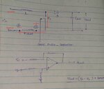
i am developing a Differential amplifier for my PFC Applications.

Here i am attaching the same.

Let me know the where the VP and VN will connect to the shunt and Why..??

i am getting confused while designing a differential amplifier.
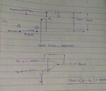
Untitled.jpg

Can i simply use the Inverting amplifier and proceed ahead.

Regards
Marx
 

Hi,

generally for non inverting output:
* Vp on the more positive terminal of the shunt
* Vn on the more negative terminal of the shunt

But your schematic is a riddle rgarding polarity.

Klaus
 

Hi,

generally for non inverting output:
* Vp on the more positive terminal of the shunt
* Vn on the more negative terminal of the shunt
Klaus
it means the posted ckt is right and VP will Connect to 2 and VN to 1

But your schematic is a riddle rgarding polarity.

Klaus

???


And why to use..?? can we do it with the Non-inverting amplifier..?

What is the significance of Differential op-amp..?

- - - Updated - - -

But if i apply the current direction then
point 2 will be more negative n so it will be connect to VN

Point 1 will connect to VP..
 

But if i apply the current direction then
point 2 will be more negative so it will be connect to VN
Wrong.

But your schematic is a riddle regarding polarity.
It becomes quite clear if you input voltage source and bridge rectifier.
 

What will be the current direction in polarity wise...
The current will flow through MOSFET.
Current will flow from point 2(-ve) to point 1(+ve)..
As per kcl.
 

The current will flow through MOSFET.
Yes. Making node 2 more positive than node 1.

Or you imagine the negative input voltage terminal connected to node 1.
 

Then the overall ckt gnd will be node 2..
 

Hi,

Then the overall ckt gnd will be node 2..
You may use any signal as GND. But you should show us in your circuit.

I assume the lower signal of the Vin or Vout is the most negative power supply line. So it makes sense to call it GND.
But still you have two choises: right side or left side of the shunt.
Only one GND symbol (in the OPAMP circuit) makes no sense at all.
Give complete informations.

Klaus
 

Referring to usual PFC circuits, node 2 (MOSFET source) is typically connect to (mains side) common ground. E.g. because it's also the gate driver and DC bus ground.

By the way, there's an unanswered question in your previous post.
What is the significance of Differential op-amp..?
You are able to measure the actual shunt voltage, not shunt voltage plus PCB voltage drop as with a single ended amplifier. (4-wire or "kelvin sensing" resistor connection)
 

Referring to usual PFC circuits, node 2 (MOSFET source) is typically connect to (mains side) common ground. E.g. because it's also the gate driver and DC bus ground.

As per stated in the comment.
Most positive will connect to the Vp and most negative to Vn..

Here i am not able to understand which point wll connect to Op-amp gnd..

Node Point 1 or node point 2..??
 

Hi,

generally for non inverting output:
* Vp on the more positive terminal of the shunt
* Vn on the more negative terminal of the shunt

But your schematic is a riddle rgarding polarity.

Klaus

Pls check the image attached of application note of IRMCF1188 Where positive signal is on the VN..
differential voltage.jpg
 

Hi,

Where positive signal is on the VN..
How can you know? The picture doesn´t show "positive signal".
You don´t show any supply polarity. --> The same riddle as in post #1.

Klaus
 

Hi,


How can you know? The picture doesn´t show "positive signal".
You don´t show any supply polarity. --> The same riddle as in post #1.

Klaus

Here i am attaching the Edited diagram
differential voltage.jpg


also for the Post #1 here is the diagram
Untitled.jpg
 

Hi,

to "difference voltage.jpg".

Now I see the more positive signal is connected to Vn...

generally for non inverting output:
* Vp on the more positive terminal of the shunt
* Vn on the more negative terminal of the shunt

Now we know the output is inverting.


Klaus
 
Now coming back to main question.
What is preferred non inverting or inverting..?
 

Hi,

I don't know.
What exactly is your expectable input voltage range?
Where does the signal go to?
What output voltage range?
Single supply or dual supply?
What accuracy do you want?

Klaus
 

Hi,

I don't know.
What exactly is your expectable input voltage range:max 100mv
Where does the signal go to:controller
What output voltage range: 0-3v
Single supply or dual supply:single supply
What accuracy do you want:

Klaus
 

Hi,

max 100mv
..is a bit vague.
Is it RMS, is it peak, is it peak-to-peak.
--> I just assume you mean 0...+100mV absolute, wrt GND.
****

Now inverting or non_inverting?
If you have positive input voltage and want positive output voltage, then non_inverting is the way to go.
****

Where does the signal go to:controller
It can be a digital IO --> not very likely
It can be a microcontroller_comparator input for fast overcurrent detection --> this is OK
It can be a microcontroler_ADC input --> OK, but you should add a low pass filter. You need to take care about: frequency range of analog signal, nyquist, sampling rate, margins at lower und upper supply rail, maybe phase shift, noise and others.
***

Single supply or dual supply:single supply
You need a rail-to-rail output OPAMP, you need an OPAMP with common mode input voltage range that includes GND. Mind that even with rail-to-rail output you will lose some mV close to GND.
***

Klaus
 
Status
Not open for further replies.

Part and Inventory Search

Welcome to EDABoard.com

Sponsor

Back
Top