Continue to Site

Welcome to EDAboard.com

Welcome to our site! EDAboard.com is an international Electronics Discussion Forum focused on EDA software, circuits, schematics, books, theory, papers, asic, pld, 8051, DSP, Network, RF, Analog Design, PCB, Service Manuals... and a whole lot more! To participate you need to register. Registration is free. Click here to register now.

How to calculate RC values for ADC filter

Status
Not open for further replies.

electric1

Junior Member level 2
Joined
Apr 23, 2011
Messages
20
Helped
0
Reputation
0
Reaction score
0
Trophy points
1,281
Activity points
1,507
Hi,

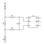
I have a typical shunt based current sensing circuit, feeding analog voltage into ADC input, then MCU reads it and logs the current values.
This device is monitoring battery charge current, which is DC obviously.
When charge source is a clean DC current, everything is fine, I get stable and correct reading from MCU.
However, when charge source is a low frequency inverter/charger, or an alternator, etc. the current is a sine wave and my ADC reads wide range of values depending on the moment ADC takes the snapshot.
If I measure voltage with DVM across the shunt, it reads correct value, corresponding to DC value stated by the charger. I assume this is RMS value of the sine wave.
I want to make an RC filter on ADC input such that ADC "sees" smooth DC value, correctly representing DC current from the charger.
How can I calculate RC values to achieve this goal?
I understand the principle of RC time constant, but struggle to understand how signal frequency effects the voltage at the capacitor, depending on capacitor value.
Sample schematic and the scope image of the charge current attached for reference.
Any help is appreciated.
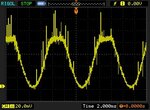
LF Charge Current.jpg
Current Sensing circuit.JPG
 

If the meter is set to the DC scale it is reading the average (which you want), not the RMS value of the AC current.

The upper limit on the AC filter is determined by how fast you want to be able to detect a change in the current level.
You then select the RC time-constant accordingly (about 5 time-constants to settle to <1% error for a new value).
 

Thanks Zapper,
I understand the upper limit, but how to figure the lower limit, which would still produce smooth enough average?
How to base the desired time constant?
I have 120 Hz wave and set R1 and R2 to 10k each, with C1 = 1uF. This makes RC time constant 50 ms ( 5 x 10000 x 0.000001 ).
My wave period is 8ms.
Yet I am still seeing too much fluctuation in ADC reading and the value seems too low.
So what is a "smooth enough average? 10%, 5%, 1%, 0.1%?

If you want my help you need to understand what I am saying.
I'll state it again.
How fast do you need to detect a change in the current?
That's what determines the maximum time-constant (and lowest LP filter corner frequency you can use).
 

So what is a "smooth enough average? 10%, 5%, 1%, 0.1%?

If you want my help you need to understand what I am saying.
I'll state it again.
How fast do you need to detect a change in the current?
That's what determines the maximum time-constant (and lowest LP filter corner frequency you can use).

Let's say I need to detect changes 10 times per second, and want average to be within 1%

I understand you and I really appreciate you taking the time and having the patience with me.
 

Why don't you use RMS-DC converter ?? Even a simple one will serve you well.
That value will be what DVM reads.
 

Let's say I need to detect changes 10 times per second, and want average to be within 1%
For 1% settling for a full-scale step in current the time-constant should be no more than 1/5 the sample period or 1/5 * 1/10s = 20ms.
Since you've already tried 50ms, and that wasn't sufficient, obviously we have a problem.
You can either reduce the settling time requirement or try a higher order active filter to achieve the desired signal purity.

Do you really need to monitor such rapid changes in battery charging current?
Wouldn't once a second or so be sufficient?

Also you could do more samples per second and take a running digital average of the samples to filter the signal.
The input analog filter would need to be below the Nyquist frequency of 1/2 the sample rate.

How large is the sinewave compared to the average?

- - - Updated - - -

Why don't you use RMS-DC converter ?? Even a simple one will serve you well.
That value will be what DVM reads.
He doesn't want the RMS of the sinewave, he wants the average value of the DC current with some AC ripple, which is what a DC voltmeter would measure.
 
Last edited:
Hi,

Why don't you use RMS-DC converter ?? Even a simple one will serve you well.
That value will be what DVM reads.
I don't recommend this. It surely gives smooth values, but wrong values.
For charging current you need the average current and not the RMS current.

I agree with Crutschow.

In detail it may become complicated. Here my mathematical/physical input

But there are different ways.
* If you want it the most flexible, then go ahead with nyquist theorem. It simply says the ADC input should contain no frequencies above half your sampling frequency. Example: If your sampling frequency is 100Hz, then all frequencies above 50Hz should be suppressed. But this does not mean you can use a low pass filter with 50Hz cutoff frequency. Because 50Hz is suppressed to 70% only. You should rather tend to 1% or less at 50Hz.
If there still is fluctuation in ADC values, then you may suppress it with software.
If you don't attenuate frequencies above half the sampling frequency, then this will cause alias frequencies. A 120Hz input signal will become a 20Hz ADC output signal when sampled with 100Hz.
This solution gives the fastest response. If you try to do a regulation loop, then you should avoid unnecessary delays to make the loop stable.

* If you want a simple solution, especially to simplify software..
If you just want to suppress the 120Hz (and higher frequency) ripple.
Let's say to 1%. (100mV ripple will be 1mV ripple).
This is a factor of 100.
For a simple RC filter take the ripple frequency and divide it by the factor (this is only true if both frequencies are enough far apart): 120Hz : 100 = 1.2Hz.
This 1.2Hz is your cutoff frequency of the RC. Let's say you have R=10k, then according fc= 1/(2 × Pi × R×C)...you need a 13uF capacitor. Use 15uF.
This filter causes a signal delay of R × C = 150ms. Even a DC input signal may take about 1s to settle to 0.5% error

In both cases...the delay time may be too big.
Then you need to use a higher order filter.

To the second example this means you need to take the squareroot of the factor: sqrt(100) = 10.
Now you need a second order filter with 12Hz cutoff. Settling time is much faster than with the 1.2Hz filter.

Klaus
 
As others have mentioned, the charging current is the average value, not the RMS value.
It is similar to the power dissipation in a diode, which is related to the average current and not the RMS current if the forward voltage is considered to be constant.

The normal way to solve the problem is to use oversampling + digital filtering in software. The requirement on the RC-filter is relaxed by the digital filtering.
If the digital low-pass filter removes 120 Hz and above, the RC filter only has to suppress frequencies that are 120 Hz and below after aliasing.
For a 1 kHz sample rate, up to 880 Hz is aliased above 120 Hz, so the RC filter only has to suppress frequencies above 880 Hz.
 

Nothing's been said yet about ADC type, sampling rate, integration respectively aperture time, input voltage range, shunt common mode and differential voltage.

You'll need at least a second order filter to achieve 100 ms response time and 120 Hz suppression to 1% residual magnitude. About 10 Hz cut-off frequency.

Yet I am still seeing too much fluctuation in ADC reading and the value seems too low.
Value too low might indicate ADC differential or common mode overload, see questions above.
 
If there is a processor, digital samples can be processed to get the average value.

Average=Sum of the samples/Number of samples that is equivalent to Integration then division to period.
A LP active filter with a pretty low cut-off frequency can be used before ADC to eliminate the high frequency spikes/glitches etc.
 
Thanks everyone for your help, I understand all the feedback and will try to adopt it to my design.
I know I could task the MCU with averaging of ADC samples, but I want to avoid it as the MCU is busy doing other work.
10 times per second was hypothetical maximum sample rate. I should be fine with even 1 time per second sampling rate.
 

Status
Not open for further replies.

Similar threads

Part and Inventory Search

Welcome to EDABoard.com

Sponsor

Back
Top