Ragnar22
Member level 1
Hi guys,
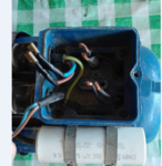
need help connection this monophasic motor because I never done this before so I just wanted to be sure that I am not going to destroy it.
I measured the resistance between the 4 conductors that come from the engine and I got:
between condutor 1 to 3 => 4,7 ohms
between condutor 2 to 4 => 7 ohms (I am assuming that this one is the starting winding)
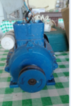
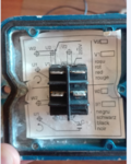
In attach I sent some photos of the motor and a photo of What I think the schematic should be, If someone could help me on this just to be sure It would be great.
Thanks guys for your time.
P.S-> I don't really understand the notation on the original schematic because it says 6 connection points, it reminds me the tri pole motors but in this monophasic motor I tought It should only be 2 windings... right?
I don't get it. :/
if someone could explain...


