Continue to Site

Welcome to EDAboard.com

Welcome to our site! EDAboard.com is an international Electronics Discussion Forum focused on EDA software, circuits, schematics, books, theory, papers, asic, pld, 8051, DSP, Network, RF, Analog Design, PCB, Service Manuals... and a whole lot more! To participate you need to register. Registration is free. Click here to register now.

Weighing Scale Design Problem

Status
Not open for further replies.

baileychic

Advanced Member level 3
Joined
Aug 2, 2017
Messages
728
Helped
56
Reputation
112
Reaction score
57
Trophy points
28
Activity points
7,033
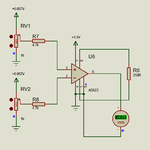
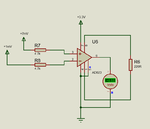
I am designing a weighing scale. I don't want to use HX711. I want to use 24-bit ADC (differential input). 3.3V excitation voltage will be provided to load cell and differential output is connected to ADC inputs.

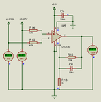
The output voltage of Load Cell is 7 mV. Should I use OpAmp with ADC. If yes, how can I use a single OpAmp to feed the difference signals and get amplified signal ?

I am using PIC18F Micrcontroller for the weighing scale.
 

hi,
You should consider a Instrumentation Amplifier,[ INA ] the AD623 will work from a single supply voltage.
E
 
@esp1

Ok but what kind of amplifier I have to design that is how to input differential voltage ?
 

hi,
The AD623 INA is specifically designed to accept low level voltage differential signal inputs, that may have a 'highish' common mode voltage.
E

EDIT:
This is an example. LTS simulation circuit
 

Attachments

  • A002.gif
    A002.gif
    32.3 KB · Views: 125
Last edited:
I am not getting the output you got. Why ?
 

Attachments

  • sshot1.png
    sshot1.png
    13.3 KB · Views: 179

What are the settings of RV1 and RV2.??

Try setting them both to their centre value, ie: wipers at 50%.
You should then measure the mVoltage between the two wipers, try to make the voltage close to zero.
Also you do not have gain setting resistor, R5 in my circuit.
E
Look at the pin numbers on my circuit.!
 
My circuit is correct. Your circuit is wrong. The pin numbers and their connections in my circuit are correct as mentioned in device datasheet. Also you can see that I have 250R gain resistor.

I referred datasheet for pin numbers.
 

RV1 and RV2 are 1k POT each. 7mV and 2mV are applied to the POT input. POT's out max are 7mV and 2mV. I need to convert 7mV to 3.3V and also to 3.3 Kgs max weight.

I set the pots as you suggested by it gives output in xx and xxx mV.

3.3V out of OpAmp is measured using ADC. Should I use 24 Bit ADC or 12 bit ADC is enough ?

3.3/1023 = 0.00322V = 0.00322 gm = 3.22 m gm minimum. I need accuracy of 1.00x gm.

3.3/4095 = 0.0008058 = 0.81 m gm
 

hi,
You are correct about the pin numbers, whoever created the AD623 model made a mistake in the numbering.!!!!
The actual internal pin assignments of model are correct for the pin locations, but not the numbers, that is why the LTS works as it should.

Did you set RV1 and RV2 as I suggested.?
E

- - - Updated - - -

hi,
This is a corrected version of the AD623 model for LTSpice.
I have drawn your variable resistors as fixed resistors and made one resistor off balance to show the output voltage from the AD623.

E
 

Attachments

  • A004.gif
    A004.gif
    29.7 KB · Views: 115
I tried the new circuit but it is giving simulation error. I am not able to simulate and see the result.

I made this calculation.

I referred this

https://forum.arduino.cc/index.php?topic=248741.0

and made the calculation

7 mV has to be amplified to 3.3V for adc input. ADC is 22-bit.

3.3V will represent 3.3 Kgs.

3300/7 = 471.428

Rg = 100000/(G-1) = 100000/470.428 = 212.57 = ~ 220 Ohms.
 

It is not working for me in Proteus. Maybe it is AD623 Proteus model bug. I will test it on hardware next week.

- - - Updated - - -

I did some tests and found that it is indeed Proteus AD62x OpAmp models bug. I switched to LTC2053. It works fine.

Here is my circuit.
 

Attachments

  • sshot2.png
    sshot2.png
    16.1 KB · Views: 96
  • sshot3.png
    sshot3.png
    30.5 KB · Views: 198

hi bailey,
A point to watch out when using a single supply voltage on the AD623 is the sense/polarity of the differential signal.
When the differential input voltage is zero and the Vref is connected to 0v. , the AD623 output will be approx +0.5v, if you have the input sense driving it the 'wrong' way, the output voltage will not get less than +0.5v.
The AD623 should be connected so that as the differential input increases the +Inp voltage becomes positive with respect to the -Inp, the output will increase in a positive direction.

If you want a differential output voltage from the AD623, set Vref to Vsupply/2, then for a 0mV input, Vout will be approx Vsup/2
The Vref MUST be supplied from a low impedance source.

With this Vref of Vsup/2, the differential input can swing +/- about the common mode input voltage. Look at the d/s for the limits of the Vout swing.
You can use the same Vref for the ADC.

I do not use Proteus so I cannot help with that version of the AD623.

E
Pleased to hear its working for you.
 

@esp1

Ok. I will try what you have said but after 1 week when I get the AD623 hardware. Proteus model has bug and hence I can't use it for testing the circuit.
 

Status
Not open for further replies.

Similar threads

Part and Inventory Search

Welcome to EDABoard.com

Sponsor

Back
Top