Continue to Site

Welcome to EDAboard.com

Welcome to our site! EDAboard.com is an international Electronics Discussion Forum focused on EDA software, circuits, schematics, books, theory, papers, asic, pld, 8051, DSP, Network, RF, Analog Design, PCB, Service Manuals... and a whole lot more! To participate you need to register. Registration is free. Click here to register now.

Analyzing a differential amplifier.

Status
Not open for further replies.

Anwesa Roy

Member level 2
Joined
Feb 24, 2014
Messages
49
Helped
0
Reputation
0
Reaction score
0
Trophy points
6
Activity points
532
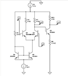
I want to perform the small signal AC analysis of the circuit. To calculate gm. I need IC ,ie the DC quiescent collector current. But in the differential amplifier stage, the AC input voltages are not connected via capacitors....So while performing DC analysis ,we cannot open circuit the AC voltage sources. Then how we are to find the quiescent collector currents?...Also even if the AC voltage sources are connected via capacitor, then while DC analysis, the base would be floating....!Please help me solve this problem.
d2.png
 

Nothing is preventing you to apply your AC signal on top of the DC biasing voltage to have oscillations around that point just by cascading the two sources. Depending on the simulator, you might in fact find a parameter named DC inside the AC generator.
In a more realistic situation you can AC couple the signal to the bias: the AC is connected through a capacitor to the input and you can connect the DC to the same node through a resistor. Now you have a time constant RC which should be much greater than the period of the lowest frequency applied to the input to perform good decoupling
 

Status
Not open for further replies.

Part and Inventory Search

Welcome to EDABoard.com

Sponsor

Back
Top