Welcome to our site! EDAboard.com is an international Electronics Discussion Forum focused on EDA software, circuits, schematics, books, theory, papers, asic, pld, 8051, DSP, Network, RF, Analog Design, PCB, Service Manuals... and a whole lot more! To participate you need to register. Registration is free. Click here to register now.
Hello,
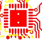
Do you know how you get rounded pads like in the attached in Eagle Pro?
I presume I will have to make them up out of 2 pads, one with rounding to 50% and the other half just plain rectangular?
You'll probably have to make a custom pad (in the library). Don't use two pads, but instead use one very small pad right in the center, then use shapes to complete the pad. In Eagle, any metal connected to a pad becomes part of the pad. When you rout, you will rout to the actual pad, which is why it is important to put it in the very center of the custom pad.
Concerning these "rounded finger pads".....
We are wanting to do a footprint for the PIC16F18856 28UQFN microcontroller. The recommended footprint is on page 652 of the datasheet…
PIC16F18856 datasheet: https://ww1.microchip.com/downloads/en/DeviceDoc/40001824B.pdf
For a small device like a 28UQFN, the rectangular pads are just fine. For larger devices, a rounded pad puts slightly more surface tension force toward the center of the pad, which makes the part more likely to center itself during soldering.
Thanks SLK001, your explanation sounds good…..the above ti.com doc, on page 2, states that the reason for the “rounded finger pads” is to prevent solder bridging between the pads.
However, I don’t know why ti.com say this, because the other end of the pad is rectangular, and so would , under their statement, be likely to suffer solder bridging? Why have they said this?
I would imagine that the application notes for all of TI's QFN packages were based on one generic document. Since bridging can be a problem for very high pin count parts (like 144QFN), you probably need the extra protection that a rounded pad gives for the higher pin count and finer pitch parts. The inner part of the pad is probably not rounded because of the geometry of the solder in this area (with the pin moving up into the device).
This site uses cookies to help personalise content, tailor your experience and to keep you logged in if you register.
By continuing to use this site, you are consenting to our use of cookies.