Continue to Site

Welcome to EDAboard.com

Welcome to our site! EDAboard.com is an international Electronics Discussion Forum focused on EDA software, circuits, schematics, books, theory, papers, asic, pld, 8051, DSP, Network, RF, Analog Design, PCB, Service Manuals... and a whole lot more! To participate you need to register. Registration is free. Click here to register now.

Power Mosfet forensics

Status
Not open for further replies.

kathmandu

Full Member level 5
Joined
Dec 7, 2015
Messages
298
Helped
7
Reputation
14
Reaction score
7
Trophy points
18
Activity points
3,146
Hello,
I need your help to investigate a recent Mosfet death.
It was one of the four paralleled Mosfets of a H-bridge high-side switch (sine wave inverter).
The Mosfet was rated at 130A (thus the paralleled group was rated at 520A), the load current was lower than 50A and I had an inline fuse (automotive type) of 90A (three 30A ones in parallel).
It seems like the Mosfet died short then the fuse has blown.
Anyway, there was no smell & smoke (there was absolutely no visible sign of damage).
Like I've just mentioned above, the drain-source jonction was dead short and I could measure a gate-source resistance (using a multimeter) of 30ohm.
Could anyone explain the cause of death?
The paralleled Mosfets were mounted on the same heatsink so I doubt there was any thermal unballance.
The Mosfet was rated at 200V, the DC link voltage was 24V and I had some 5kW TVS diodes (110V) across that DC link, too.

Could have been a manufacturing issue? Btw, I'm pretty sure it was a genuine part (sourced from Mouser).
Any other ideas?
 

Hi,

Most MOSFET failures I've see had two failure sources:
* overheat by too much power dissipation. Either for long time, or for short time
* overvoltage. Caused by spikes.

In your case I assume overvoltage. TVS usually are fast. But they need a low impedance current path.

A schematic, a PCB layout, additional information like timing...is essential if you need more assistance.

Klaus
 
Thank you for your quick support, @Klaus!

It'a regular H-bridge driven by high performance IC drivers (TC4422A). Btw, the power Mosfet it's a IR (now Infineon) product: IRFP4668.
The switching frequency is 20kHz and the deadtime is around 300ns.

I was wondering if that clue alone ("silent" death - no smell & smoke- and only one of a paralleled group of four was affected) were enough to guess the cause of death.

I've only seen Mosfets dying in flames(!) in my limited power electronics journey.
 

Hi,

The given MOSFET is an N-ch type.
The given driver is for low side only.
I wonder how you drive the high side MOSFETs.

It's a waste of time without the requested informations.

Klaus
 

I'm using individual (isolated) power supplies for each H-bridge switch driver.

That's it, I'm using low side drivers and N-channel Mosfets for every H-bridge switch

What additional infos should I provide? The whole circuit ran for a year and a half continuously (24/7).
 

Hi,

Read post#2.

Klaus
 

I don't know what further information do you need. It's a four switch bridge, do I have to post a picture of it??
The four paralleled Mosfets are symmetrically placed around the PCB so there's no "weak link". The DC link capacitors (and the TVS) are placed right beside the Mosfets.

Anyway, I guess I know why there was no smoke & stuff like that: the fuse has blown in no time, right after the Mosfet has shorted out. That alone has limited any further damages of the Mosfet package (melting, burning and such).

I just thought that a Mosfet "corpse" may look different if he died because of an overvoltage (drain-source), overcurrent, overheating or because of a gate-source overvoltage, by example.

In my particular situation, I have a shorted drain-source jonction and a 30ohm impedance between the gate and the source terminals. Does it mean anything?
 

do I have to post a picture of it??

You have not to do it, just do if you want, but the more information you provide, the more chance of being successful in getting help to identify some possible cause of the problem. The fact that it has worked for a long time does not necessarily mean that the project is flawless, it could be working exceding some of its specifications or at least could be not protected as should be ( or even could be happening some circumstantial event, not easy to detect ). Anyway, adding more information it is not a guarantee that anyone will identify something, but it only increases the chance of this happen.

I know why there was no smoke & stuff like that: the fuse has blown in no time, right after the Mosfet has shorted out. That alone has limited any further damages of the Mosfet package (melting, burning and such).

In fact, but it is a strong indication of a short circuit on its output. At least it would be the start point to seek in my oppinion.
 
@andre_teprom:

You're right, I have not fully protected the inverter. The fastest active protection are the TVS (for overvoltage spikes) and the inline automotive fuse (overcurrent). I actually have an overcurrent protection designed in a software routine (by reading a Hall current sensor) but the polling period is quite long (10us) hence it doesn't actually react during this recent fault condition.

I'll have to redesign the software routine to continously read the current sensor output an to set a hardware interrupt when the overcurrent occurs, to cut the gates signal.


PS:

Oh, I forgot to mention that I found the source of the output overcurrent (overload). I've detected some burned wires (shortcircuited) on an outdoor equipment, inside a connection box (water leaks, most probably).

Btw, the fuse has done it's job when I once tested it with some decent overload but it was definitely not fast enough for this shortcircuit condition.

Thinking in numbers: if this Mosfet has died of overcurrent condition, it was rated at 130A and I had 4 of them in parallel, then the total (shortcircuit) output current was greater than 500A and that 90A fuse didn't react that fast? Speaking of that, is there a Mosfet parameter to indicate its overcurrent behavior (amplitude/duration)?

That's the Mosfet datasheet: https://www.infineon.com/dgdl/irfp4668pbf.pdf?fileId=5546d462533600a40153562c8528201d.
 
Last edited:

I believe there is no way to ensure that the Rds(on) values on each device in the array are symmetric to, so that at the time of the short-circuit event, one of them might have faced most of the overload alone and burned immediately, while the others were burning in the sequence, each one much more overloaded for the each other which got out.
 

You know what's the best part? The first shorted out Mosfet has protected the rest of the "pack": its low impedance path (drain-source short-circuit) took over the overload current until the fuse blew out.

Anyway, what's supposed to be the fastest method for short-circuit protection in this current range (100A)?.. and how fast it actually should be to be effective??
 

As Klaus have mentioned above, without having any information about your circuit we haven't any clue of the options available. The standard solution is to use a comparator reading the shunt resistance common to all MOSFETs, and the resulting output, trigger the shutdown/reset input of the MOSFET driver circuit ( assuming you are using some IR2110's relative or another integrated solution ).
 

Thank you very much for your suggestion, I'll design a shunt based protection. But how do I know if my protection circuit will be fast enough? What parameter/diagram should I look after in the Mosfet datasheet?
 

The fuse is only there as a measure of last resort to prevent a fire. It is way to slow to completely protect a semiconductor.

Mosfets usually have on their datasheet non-repetitve current ratings, which indicate xxx current they can withstand for yyy microseconds.
Warning! These curves are almost always shown at 25C junction temperature. If the device junction (which will always be many degrees warmer than the actual heatsink temp), that rating will be significantly reduced.

To make a long story short............for optimal protection, you need a two step electronic protection scheme.

The first step is to instantaneously shutoff the Mosfet if an overcurrent spike several times the maximum rated current appears.
The second step is to allow a delay (measured in tens of milliseconds) if the current spike is slightly above normal.

There are significant calculations, simulations and actually lab measurements required to get this right.
 
My H-bridge has a low-frequency transformer as load. The short-circuit occurred on the transformer secondary side. How was this translated to the transformer primary current (the Mosfets drain current)?

Being involved a large inductor (primary winding), the change in that inductor current could not have been too abrupt. That means it took some time (maybe miliseconds? ) for this current to reach a dangerous value. During this time, the fuse should have blown.

Am I missing something? Could someone please explain this process of shorting out the transformer secondary and its effect on the primary current??

Later edit:

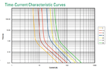
Looks like the car fuses are way too slow:
car-fuse.png
 

Hi,

Being involved a large inductor (primary winding), the change in that inductor current could not have been too abrupt.
This inductance current is in parallel to the load current.
You talk as if it was in series.
In series ther is only a small stray inductance

Time delay is much smaller than in your assumption.

Klaus
 

I was talking about the Mosfets being in series with the primary inductance.
The consideration is wrong, though. Only transformer leakage inductance is reducing the short circuit current slew rate, not primary inductance. Sketch a transformer equivalent circuit for analysis.
 
I could sketch a transformer but I still prefer some "text based" explanations. ;)

Thanks in advance for any detailed answer.
 

This is the equivalent circuit.
What happens if you short the secondary?

Hint: the primary inductance is the parallel arm.

Untitled.png
 
Status
Not open for further replies.

Similar threads

Part and Inventory Search

Welcome to EDABoard.com

Sponsor

Back
Top