Continue to Site

Welcome to EDAboard.com

Welcome to our site! EDAboard.com is an international Electronics Discussion Forum focused on EDA software, circuits, schematics, books, theory, papers, asic, pld, 8051, DSP, Network, RF, Analog Design, PCB, Service Manuals... and a whole lot more! To participate you need to register. Registration is free. Click here to register now.

Quality factor of inductor

Status
Not open for further replies.

promach

Advanced Member level 4
Joined
Feb 22, 2016
Messages
1,199
Helped
2
Reputation
4
Reaction score
5
Trophy points
1,318
Activity points
11,636
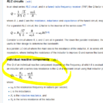
Why is R=QLw ? I suppose R=Lw/Q ?

Screenshot from 2017-08-05 11-14-38.png


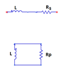
There are two different R here

Series R (Rs) and Parallel R (Rp)

lr.png

For Series R:

Rs= LW/Q

For Parallel R:

Rp=QLW

How you calculate Q for two component network, write this down somewhere:


Q= Imaginary (Z) / Real (Z) -----> For series

Q= Imaginary (Y) / Real (Y) -----> For parallel


In the example you mentioned it is talking about parallel R which is Rp
 
Last edited:


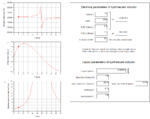
Don't look at the resonator math, because this is an inductor only, and we want to get the inductor Q. This is done by evaluating the impedance and interpret it as series RL. In this calculation, existing parasitics will be cause a frequency dependent L and frequency dependent R. Q factor is calculated from that L(f) and R(f).

QL.PNG

Practical RFIC example with Q(f), L(f) and R(f):

RLQ.PNG
 
Last edited:

Q= Imaginary (Z) / Real (Z) -----> For series

Q= Imaginary (Y) / Real (Y) -----> For parallel

@Ata_sa16 Could you shed more lights on these two statements above ?

I have found a simple explanation but "inductor stores energy half the time and releases the energy the other half."

PvKJYIH.png

Extracted from https://physics.stackexchange.com/a/109749
 

Attachments

  • Screenshot from 2017-08-06 20-12-42.png
    Screenshot from 2017-08-06 20-12-42.png
    94.2 KB · Views: 75

@Ata_sa16 Could you shed more lights on these two statements above ?

I have found a simple explanation but "inductor stores energy half the time and releases the energy the other half."

PvKJYIH.png

Extracted from https://physics.stackexchange.com/a/109749

you have completely misunderstood the Q here. S=P+j*Q here Q is not the same Q
This Q is reactive power not quality factor.

Do you know complex power ? this is totally different topic.

- - - Updated - - -

As I mentioned in previous post. For now just forget about VCO and start reading about fundamental concepts like:

1) What is Quality factor? why it is important ? what is it relationship with Loss and Noise.
2) Quality Factor in two component networks (R-L and R-C series and parallel)
3) Quality factor in RLC resonant circuit (It is not the same Q as two component network)

- - - Updated - - -

Maybe this helps you

https://www.electrical4u.com/quality-factor-of-inductor-and-capacitor/

Then the maximum energy stored in the inductor is written in terms of current

For parallel R-L you may use similar approach but this time rewrite terms in terms of voltage you will reach my formulae

Q= Imaginary (Z) / Real (Z) -----> For series

Q= Imaginary (Y) / Real (Y) -----> For parallel

It is not really important and necessary to know where are they coming from all you need to know is 2 formulae I have provided
 
Last edited:

Rp=QLW = (10*1nH*10GHz) != 630
 

Do you know w=2*pi*f ??? 8-O

you put w=10 GHz !! :shock:

You need to learn/review fundamental concepts before designing VCO.

1.2K is Rp of 2 inductors, here for calculations we need half of the circuit. As it is written fig.8.18

You need to read the book carefully.
 
Last edited:

Status
Not open for further replies.

Part and Inventory Search

Welcome to EDABoard.com

Sponsor

Back
Top