Continue to Site

Welcome to EDAboard.com

Welcome to our site! EDAboard.com is an international Electronics Discussion Forum focused on EDA software, circuits, schematics, books, theory, papers, asic, pld, 8051, DSP, Network, RF, Analog Design, PCB, Service Manuals... and a whole lot more! To participate you need to register. Registration is free. Click here to register now.

Diode Resistance in MOSFET bridge

Status
Not open for further replies.

abhishek.2138

Full Member level 2
Joined
Dec 21, 2013
Messages
131
Helped
0
Reputation
0
Reaction score
1
Trophy points
1,298
Activity points
2,383
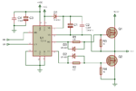
In IGBT/MOSFET H-bridge for AC drive or inverter power circuit, generally 1N4148 diodes are connected to gate terminals for adjusting the turn-off time.

How to calculate the diode resistance in this case?? Circuit is attached...(Here resistances for D2 & D3)

Can we use 1N4148 in place of UF4007?

I calculated the resistance as per the diode formula , but it comes in milliohms. I have doubt about the calculated values...

References-- **broken link removed**

**broken link removed**

Please help...
 

Attachments

  • IR2110 block.png
    IR2110 block.png
    44.7 KB · Views: 225

IN4148.png

IN4148 is also fast switching diode, its revers recovery time is 8ns but for UF4001 has 75ns. 1N4148 is not good for above 500KHz switching frequency

Diode resistance can be calculated by

DC R = 1V/300mA = 3.3 Ohms
 
  • Like
Reactions: sheerry

    V

    Points: 2
    Helpful Answer Positive Rating

    sheerry

    Points: 2
    Helpful Answer Positive Rating
Hi,

I see it the other way round:
* the resistor determines the ON time delay. The turn ON current is (mainly) determined by the resistor.
* the diode makes a fast turn OFF. The turn OFF current is (mainly) determined by the driver's capability.

Klaus

Added:
The "recovery time" of a diode is the time between conductive and non_conductive mode. It is the time to become high impedance.

In the gate driving circuit this item is not important:
* the diode becomes conductive when the driver switches the gate_source voltage down.
* but usually the driver is LOW for a while = the MOSFET is OFF.
* during this time the "recovery time" of the diode comes into account
* the diode usually has plenty of time to become high impedance. The charge will flow through the parallel resistor.
* but even if the diode still is conductive when the driver begins to turn ON the MOSFET...it just makes the turn_on a tiny bit faster. I assume it is in the range of high picoseconds...below 1ns.

The smaller the OFF_time of the MOSFET the more critical is the recovery time. I assume in most cases the OFF time is more than 100ns and therefore you won't see a difference between 1N4148 and UF1007.

But UF1007 can carry a lot more pulse current with less voltage drop than the 1N4148.

***
DC R = 1V/300mA = 3.3 Ohms
True. But the resistance is very nonlinear. It depends on current.
Therefore you can't use this value to calculate a delay time according "R x C" or similar.
 

    V

    Points: 2
    Helpful Answer Positive Rating
Resistance selection in this circuit has nothing to do with diode characteristic or "diode resistance". It's chosen according to intended turn-on time and/or turn-on delay. There are mainly two objectives:
- avoiding bridge shoot-through (poor man's dead time generation method)
- adjusting the drain current and voltage rise time to reduce EMI and keep transistor dV/dt ratings

Regarding diode selection, 1N4148 isn't well specified for IR2110 peak current of 2A.
 

    V

    Points: 2
    Helpful Answer Positive Rating
Hi,

I see it the other way round:
* the resistor determines the ON time delay. The turn ON current is (mainly) determined by the resistor.
* the diode makes a fast turn OFF. The turn OFF current is (mainly) determined by the driver's capability.

Klaus

Added:
The "recovery time" of a diode is the time between conductive and non_conductive mode. It is the time to become high impedance.

In the gate driving circuit this item is not important:
* the diode becomes conductive when the driver switches the gate_source voltage down.
* but usually the driver is LOW for a while = the MOSFET is OFF.
* during this time the "recovery time" of the diode comes into account
* the diode usually has plenty of time to become high impedance. The charge will flow through the parallel resistor.
* but even if the diode still is conductive when the driver begins to turn ON the MOSFET...it just makes the turn_on a tiny bit faster. I assume it is in the range of high picoseconds...below 1ns.

The smaller the OFF_time of the MOSFET the more critical is the recovery time. I assume in most cases the OFF time is more than 100ns and therefore you won't see a difference between 1N4148 and UF1007.

But UF1007 can carry a lot more pulse current with less voltage drop than the 1N4148.

***

True. But the resistance is very nonlinear. It depends on current.
Therefore you can't use this value to calculate a delay time according "R x C" or similar.

Thank you...
Though diode has small resistance, but we need to consider diode resistance while selecting turn-off gate resistor value. Suppose driver VCC = 15V and has 400 mA sink current capacity and 39 ohm resistor connected in series with the diode. Then, voltage drop across 39 ohm will be 15 V (if we consider ideal diode) but practically the diode will offer some resistance. For this how to calculate diode resistance value so that I can select right value of resistor to be connected in series with diode. For example if diode offer 3 ohm resistance then its easy to choose 36 ohm resistor to be connected in series with the diode...
 

Hi,

Why do you want to use a resistor in series with the diode?

Klaus
 

I see that you asked about adjusting the turn-off time in post #1. Unfortunately the schematic doesn't show a respective series resistor, so we overlooked the point.

The actual turn-off time is determined by a combination of mostly non-linear component characteristics. It's difficult to calculate it exactly, better use a simulation, or preferably adjust it empirically in the real hardware.

It's a bit unusual to have diode series resistors. Instead the driver output current and possibly the diode resistance are chosen respectively.
 
Hi,

Why do you want to use a resistor in series with the diode?

Klaus


I want to use resistor in series with diode for limiting the sink current from MOSFET gate so that the driver's current sink capacity is not exceeded. If only diode used i think driver may get damaged.
Is it right??
 

Hi,

MOSFET driver IC´s are desigend to drive capacitive loads.
Usually the current is limited by the driver IC, so you don´t have to limit it externally.

Klaus
 
Hi,

MOSFET driver IC´s are desigend to drive capacitive loads.
Usually the current is limited by the driver IC, so you don´t have to limit it externally.

Klaus


Thank you. But that means the gate resistor selection criteria is only to adjust the turn-on and turn-off times of MOSFETs rather to limit the driver's sink or source currents. If it is then how to calculate the optimum gate resistor value??

Should I follow the calculations as per https://www.electronics-tutorials.ws/rc/rc_1.html ???
 

Hi,

The MOSFET manufacturers and driver IC manufacturers have lots of good documents.
Go to their internet sites and look for relating application notes.

Klaus
 

Status
Not open for further replies.

Similar threads

Part and Inventory Search

Welcome to EDABoard.com

Sponsor

Back
Top