Continue to Site

Welcome to EDAboard.com

Welcome to our site! EDAboard.com is an international Electronics Discussion Forum focused on EDA software, circuits, schematics, books, theory, papers, asic, pld, 8051, DSP, Network, RF, Analog Design, PCB, Service Manuals... and a whole lot more! To participate you need to register. Registration is free. Click here to register now.

Tesla Coil Drsstc Simple Circuit Schema

Status
Not open for further replies.

devreci

Junior Member level 1
Joined
May 25, 2014
Messages
15
Helped
0
Reputation
0
Reaction score
2
Trophy points
1
Activity points
114

basic_tesla_coil_drsstc_circuit_schema.JPG
 

Do you power it directly from 230V (or may 120V?) socket, or through the transformer?
 

Yes, need 50v----300v another dc power.

If used 50v , 50n06 75n06 irfz etc cheap 60v mosfet can be used for flourecance lamp light up ,but if out capacitor 500nf --- 1uf 5cm..10cm spark to screwdriver.
 

Why?
Did you try powering it directly from 230V (or 120V, I don't know your location) socket?

Anyway, I saw your photos of MOSFET/IGBT connections on the youtube, and you have very long wires. This will shorter the live of the MOSFETs. I think you should prepare a proper PCB for entire circuit
 

Yes i used 220v Ac. Bridge rectifier and capacitor -> 300v dc

50v--100v etc need for test. 24v transformator for test. (different in the video)

Why?
Anyway, I saw your photos of MOSFET/IGBT connections on the youtube, and you have very long wires. This will shorter the live of the MOSFETs. I think you should prepare a proper PCB for entire circuit

Twisted cable has low inductance (a similar coaxial cable) long wire can use
 

Do you have access to osciloscope?
I'd like to see the waveforms at the MOSFET gates and the primary coil waveform.
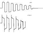
Why are you using no gate resistors at all? Are they not necessary?
 

Why are you using no gate resistors at all? Are they not necessary?

If the gate driver produces strong and good square wave, door resistance is required for protect gate driver or mosfet.

But resistor not need in this circuit.Because gate driver strong and produce a little sinusodial wave.


Do you have access to osciloscope?
I'd like to see the waveforms at the MOSFET gates and the primary coil waveform.

I remember this.

erteter.JPG
 

Those peaks you showed might be dangerous for mosfets, but maybe I will try to replicate your design soon.

What is the power consumption at 220V mains supply?
also, did you try it with normal (non-audio) interrupt? Is it able to work without overheating for a longer time?
 

Those peaks you showed might be dangerous for mosfets

Maybe not, very small signal and maybe 500-600v

What is the power consumption at 220V mains supply?

1W to more KW , It depends sound frequency and out capcacitor.

Sound interupt frequency must 1HZ to 1-2khz

As the frequency increases, the capacitors warm up (igbts low warming).

Need cooler water or oil, or use 10KV high voltage capacitor, I used 1200v and they are warming.


I will try to replicate your design soon.


You can try test this cheap circuit for exprenimnatal.


first_test_tesla_coil.jpg
 

İf transformer 16v not need regulator, if transformer 24v 18v yes you must use.

For the gate voltage, mosfet or igbt gate voltage must be min 11V --- max 20v.

aaaa.JPG
 

Status
Not open for further replies.

Part and Inventory Search

Welcome to EDABoard.com

Sponsor

Back
Top