Continue to Site

Welcome to EDAboard.com

Welcome to our site! EDAboard.com is an international Electronics Discussion Forum focused on EDA software, circuits, schematics, books, theory, papers, asic, pld, 8051, DSP, Network, RF, Analog Design, PCB, Service Manuals... and a whole lot more! To participate you need to register. Registration is free. Click here to register now.

Modulator from VCR - works only when in VCR?

Status
Not open for further replies.

Garyl

Full Member level 5
Joined
Mar 28, 2017
Messages
253
Helped
6
Reputation
12
Reaction score
7
Trophy points
18
Activity points
2,633
Hello.
I have a PAL signal source and I wanted to modulate it to the 30~~ Channel..
I have a VCR (Videocassette recorder) which outputs signal on 30-40 channel.
It works and generates WHITE BARS when in test mode.

I wanted to use the PAL signal modulator from VCR to modulate my PAL signal into the TV aerial output.

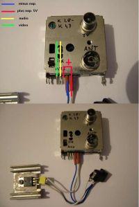
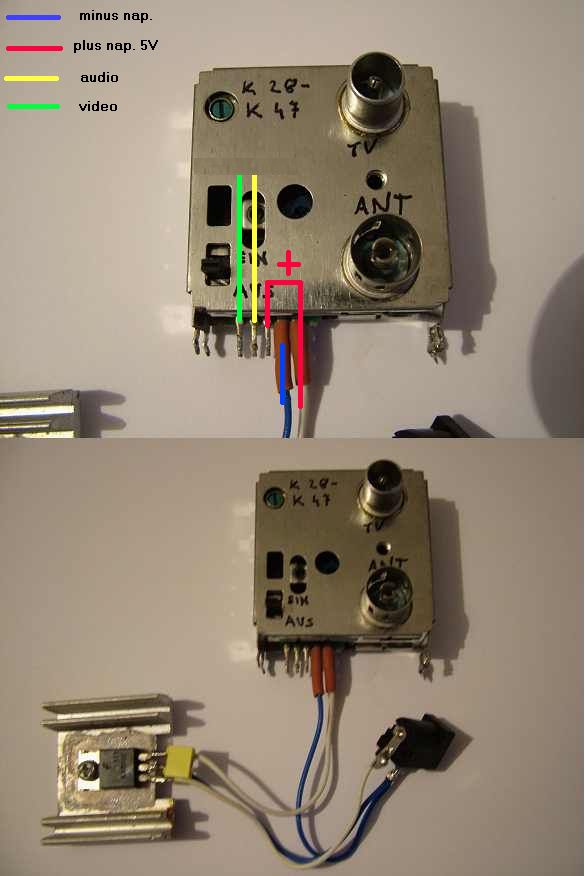
I have opened VCR, found the modulator, and tested that it has following pins:
1. Video
2. Audio
3. VCC 5V
4. Disconnected / ground
5. VCC 5V

And the case is GND.

I then I have made three tests:
1. I have soldered camera PAL input to VIDEO pin (and ground to ground) and turned VCR on. It worked, modulator output was the image from the camera.
2. I have turned VCR off (unplugged it) and added external 5V source to the 3 and 5 pin. It worked, modulator output was the image from the camera.
3. I have desoldered the modulator module from the VCR, connected it to 5V source and video signal and.... the camera video is black! But the test white bars are working. WHY??
4. I have soldered back the modulator to VCR to see if I damaged it, but no - it works perfectly in VCR in the configurations from points 1 and 2.

This is the reference image (but not mine, altough my modulator is very similiar):


My question is: What am I missing? Why this modulator is not modulating my video signal when outside the VCR (but it's correctly generating test white bars)?
 

Did you terminate the camera output?
When checking in the VCR was there any DC on the video input pin that might have come from somewhere else?

The most likely scenario is the camera video output has some DC superimposed on it and it is upsetting the modulator. The camera output should be 1V peak-to-peak video signal into a 75 Ohm load with no DC on it. You can try adding a 75 Ohm resistor across the camera output (output to ground) and coupling the video to the modulator input through a large electrolytic capacitor (at least 220uF) to remove any residual DC. Most likely the '+' end should be toward the camera.

Brian.
 
  • Like
Reactions: Garyl

    Garyl

    Points: 2
    Helpful Answer Positive Rating
I've added a 100 ohm resistor between VIDEO and GROUND and both of my modulators started working immediatelly!

Thank you very much!

The case is almost resolved, altough I didn't use capacitor - how would I connect it? '+' towards the camera (and to the resistor)?
Is it possible that the same issue (wrong camera output?) was causing my single-transistor TV transmitter to fail?
 

I'm glad it worked!

To understand why it didn't work before and why the capacitor might still help you have to look at the way a video signal is produced. It isn't like audio where there is only one analog stream, a television signal also has synchronizing signals added to it, they are to make sure the monitor scan exactly follows the camera scan or the image would be out of place on the screen. The picture is divided into thin lines, you have probably seen references to 525 or 625 line standards, these are the number lines that make up the complete picture. The lines scan from left to right and also move from top to bottom of the picture at a slower rate, 50 or 60 times a second, the speed is fast enough that our eyes perceive it as a complete picture even though it is really just a single spot of light.

The problem becomes how to make the picture visible (obviously) but hide the synchronizing pulses. The method used is to base the black parts of the picture as 0V and make the sync signals negative. A bright part of the picture would be positive and the syncs negative with respect to ground. Technically, there is no problem with that and it has worked for many years. However, those cheap cameras, and many more expensive ones, work from a single positive supply so they have no way of producing an output that goes below 0V. That would seemingly make it impossible to produce the sync signals, the way they get around it is to 'lift' the entire video and sync signal to a fixed positive level. For example, instead of the video going from +0.7V to 0V and the sync going from 0V to -0.3V (1V in total) they might make the video go from 2V to 1.3V and the sync from 1.3V to 1V, still the same signal but lifted so the original 0V is now 1.3V. It is then possible for the camera to produce video and sync from the single power line.

The consequence of that is the camera video now has some positive voltage on it all the time, 1.3V in the example above and it can upset any circuitry it is connected to. Additionally, the output stage in the camera often relies on there being a load to produce the voltage correctly. Standard video is produced at 2V peak to peak then fed through a divider circuit to match it to standard cables. The divider is a 75 Ohm resistor in the camera and an external 75 Ohm resistor to ground outside the camera. They halve the voltage from 2V to 1V but more importantly, if you use standard video co-axial cable to carry the video, it makes sure both ends are terminated properly to avoid distortion. The external 75 Ohm resistor goes at the far end of the cable from the camera, usually in the monitor/TV or recorder. If those resistors are not there, often the output stage of the camera will not work, similarly some devices, like the modulators you tried, may not work if the DC 'lift' is present so a blocking capacitor is necessary to remove the fixed voltage.

If you do need the capacitor, it goes between the load resistor and the modulator and almost certainly should have it's positive end towards the camera.

Brian.
 
  • Like
Reactions: Garyl

    Garyl

    Points: 2
    Helpful Answer Positive Rating
Status
Not open for further replies.

Part and Inventory Search

Welcome to EDABoard.com

Sponsor

Back
Top