T
treez
Guest
Hello,
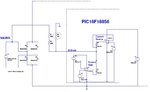
The Zero crossing detector in PIC16F18556 detects zero cross as when the current into the pin goes below 100uA? Do you agree?
PIC16F18856 Datasheet (pg314 discusses zero cross detection)
https://ww1.microchip.com/downloads/en/DeviceDoc/40001824B.pdf
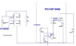
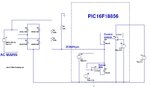
The Zero crossing detector in PIC16F18556 detects zero cross as when the current into the pin goes below 100uA? Do you agree?
PIC16F18856 Datasheet (pg314 discusses zero cross detection)
https://ww1.microchip.com/downloads/en/DeviceDoc/40001824B.pdf