wizpic
Advanced Member level 3
I'm looking into creating an external add on alarm for my van without an extra keyfob on the key ring, has it as been known for someone can open all doors with setting the factory fitted alarm off. The indicators flash twice when I double lock it, I think the flashes are 250/500Ms seconds apart and then when I unlock it gives a signal flash about 1 second long, my idea is to use and micro-controller to capture this signal to enable me to turn it of/on with having to keep remembering to turn it on. May I add an ultra sonic or infrared sensor along with 2 micro switch for the trigger if the rear doors open.
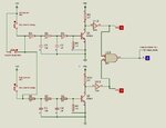
What I'm looking for is the best way to create an input filter from the indicators from 12v to 5v and give a clean switch signal, I've tried with an resistor divider with a low pass filter but with the length of the wires I seem to get a false spike which sets it off. At the moment I'm only recording and testing without any sounder so I can see what heppening.
Once I've managed to sort out the input filter I than can capture the full lengths of the flashes of the indicators.
I'm sure I seen some where using a schmitt trigger but not 100% sure how to do it
So any recommendations to achieve a clean switching signal from the indicators
Thanks
