cartman007
Member level 2
HI everyone.
I received this question to do.
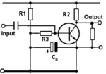
My first question is, Is this an normal Emitter follower circuit when the output is take from the Collector?

Also what do they mean if they say I have to bootstrap this Amplifier without giving me any values for the components?
I dont understand the question.
Thanks
I received this question to do.
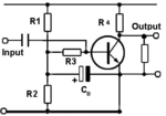
My first question is, Is this an normal Emitter follower circuit when the output is take from the Collector?
Also what do they mean if they say I have to bootstrap this Amplifier without giving me any values for the components?
I dont understand the question.
Thanks