Continue to Site
Follow along with the video below to see how to install our site as a web app on your home screen.
Note: This feature may not be available in some browsers.
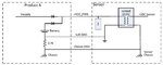
1. You can connect the TVS diode to the chassis on sensor block.
2. In product A:
The signal grounds of the Analog circuits are not allowed to be connected to the chassis, which depends on the system architecture, a combination of resistor (1Mohm) and capacitor (xx nF) (even with diode) are used to prevent ground loops as well as parasitic feedbacks between the circuit and the chassis.
The rational behind the value of 2.7kOhm may be specific compliance with any Standard requirements (for Eg CE).
If the soft ground and the chassis are shorted to make it absolutely safe, we may have a ground loop. This may cause performance problems. To minimize the ground
loop current, they suggested to use a 2.7kohm ( I hope that the value arrived based on the analysis on physical system) resistor to connect grounds together. This reduces ground currents to virtually eliminate them.
Do i need to add TVS between Soft-GND to Chassis GND ?
TVS Diode is not required between Soft-GND to Chassis.
If the Sensor product is not connect to Product A and there is ESD signal at Soft GND, Will it damage the sensor ?
Doron