Continue to Site

Welcome to EDAboard.com

Welcome to our site! EDAboard.com is an international Electronics Discussion Forum focused on EDA software, circuits, schematics, books, theory, papers, asic, pld, 8051, DSP, Network, RF, Analog Design, PCB, Service Manuals... and a whole lot more! To participate you need to register. Registration is free. Click here to register now.

Clip light circuit for audio signal

Status
Not open for further replies.

Enzy

Advanced Member level 1
Joined
Mar 20, 2016
Messages
488
Helped
2
Reputation
4
Reaction score
2
Trophy points
18
Activity points
4,607
I have seen a couple clip light circuits online and tested them out and they don't seem to work, what I had in mind was to build a simple circuit with just 2 leds one to show signal and the other for when the signal is clipping I have seen that on amplifiers but the circuits aren't really easy to find online.

I have been checking out some opamp videos as far as I see a voltage follower circuit with a diode and a cap at the output can be used as a clip light detector not sure if it is practical though.

- - - Updated - - -


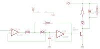
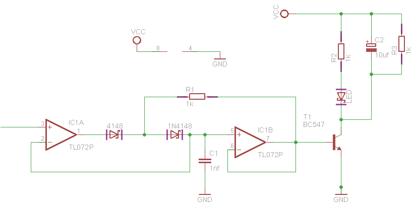
That's a sketch of what I had in mind
 

The circuits seems flawed in several regards.

- missing discharge path for C1
- missing current limiting resistor for T1 base current
- TL072 isn't suited for single supply operation

In addition
- what's the intended function of C2/R3?
- what's purpose of R1 and first 1N4148? Seems useless at first sight.

- - - Updated - - -

A reasonable clip monitor should act on both polarities (full wave rectifier), have a precise comparator threshold and extend the comparator signal by a fixed time amount.

- - - Updated - - -

Despite what I suggested previously, here's simple overload detector circuit of a Rane ME60S graphic equalizer. +/-15V OP supply, detecting overload at filter input and output.

Rane ME60S OL-detector.png

With a threshold around 7 - 8 V, the LED lights up already below clipping level.
 

So at R7 and R8 thats where the inputs connect to?
 

Yes. They connect to OP outputs of the equalizer input and output amplifier.
 

Hi,

A true clip detector is at the input and feedback signals of an amplifier.

If you don't have access to the feedback signal, then it is only a level detector, because it can not detect if clipping occurs or not.
True clipping depends on power supply fluctuations, load current...maybe signal frequency if there is a dV/dt limit, that causes similar audible noise and similar spectral errors than a voltage clip.

Klaus
 
  • Like
Reactions: Enzy

    Enzy

    Points: 2
    Helpful Answer Positive Rating
Status
Not open for further replies.

Similar threads

Part and Inventory Search

Welcome to EDABoard.com

Sponsor

Back
Top