Continue to Site

Welcome to EDAboard.com

Welcome to our site! EDAboard.com is an international Electronics Discussion Forum focused on EDA software, circuits, schematics, books, theory, papers, asic, pld, 8051, DSP, Network, RF, Analog Design, PCB, Service Manuals... and a whole lot more! To participate you need to register. Registration is free. Click here to register now.

Build a constant current circuit

Status
Not open for further replies.

Bjtpower

Full Member level 5
Joined
Dec 24, 2015
Messages
297
Helped
2
Reputation
4
Reaction score
2
Trophy points
1,298
Activity points
3,893
Hello friends

I look forward to build a circuit which will provide me a constant current to end application.

input voltage:60v

Constant current will be 300mA

Look forward your idea towards implementations


Regards
Marx
 

Hi,

You have several choices.

Op amp + reference voltage + MOSFET (or BJT) + shunt. These seem to be pretty reliable for hours.

BJT + LED current source I made and used one of these at 5V and 100mA and it has been sufficiently reliable for uses of a few minutes at a time (no idea how reliably they regulate the current last if on 24 hours) - derated a lot, e.g. 5W resistors and medium power BJT.

Discrete, e.g. Wilson current mirror. No reason not to make one with medium/high power BJTs. I guess it may depend on the load. If your load changes a lot then this kind may not be as constant as the op amp + MOSFET type.

There are other types as well, obviously.
 

Hi,

I think linear regulators are not very suitable for 60V, 30mA, because this means max 18W of power dissipation.

I recommend a step_down = buck regulator.
Modify the feedback to get a current limit function instead of voltage regulation.

Klaus
 

Hi,
i want to make a circuit which can provide a 60V @30mA OF current

as well 5v@300 ma in the same output

But for 30mA, Voltage drop would be very low
and for that i will have to again amplify the same and apply to the Amplifier to amplifiy then it would drive the BJT.
IT WOULD BE VE VERY LONG METHOD.

i want to make it with a cost effective as well low circuitry.

I am attaching my architecture with this.
cclimit.jpgcc ckt.jpg
 

Operating a linear current source over a dynamic range of 1:10 (30 - 300 mA) is no problem at all. You didn't yet specify accuracy requirements however.

I read the block diagram so, that you plan to switch the power supply between different voltage and current ranges so that the output transistor power dissipation can be minimized.

I think linear regulators are not very suitable for 60V, 30mA, because this means max 18W of power dissipation.
1.8W according to my math.
 
Hi,

1.8W according to my math.
True, for sure.
My typo was 30mA instead of 300mA. For 300mA (OP, post#1) the 18W are true.
In post #6 the OP reduced it to 30mA at 60V.

With the new information of the OP 1.5W/1.8W are true.

But how to ensure that the limit is 30mA ... with an extra comparator for the voltage?

Klaus
 

Operating a linear current source over a dynamic range of 1:10 (30 - 300 mA) is no problem at all. You didn't yet specify accuracy requirements however.

I read the block diagram so, that you plan to switch the power supply between different voltage and current ranges so that the output transistor power dissipation can be minimized.


1.8W according to my math.

Hi FVM

Accuracy will be 5%
and how to switch the individualyy

At a time only one will be the output
60v@20mA OR 30V@30mA OR 5V@300mA

Will the opamp with bjt work.. and how..??

I want to control it through Microcontrollers
 

i was reading and i am understanding that
if i keep the VGS Constant irrespective of load will it work in cc mode.

Picture attached here
Let me know your suggestions
IMG_20170721_172627.jpg
 

MOSFET has roughly constant current with constant Vgs, but for accurate current source a feedback circuit like the previously presented OP circuit is required.
 
But for a 20ma.. how we can sense
 

Hi,

Hope this is what you mean... For the op amp + Vref + MOSFET + Rset, the voltage that develops across the shunt should equal the reference voltage. e.g. If a 1.25V reference is used, for 20mA the Rset would be 62.5 ohms.
 

Assume a 1 ohm shunt, 20 mA gives 20 mV, 5 % accuracy means 1 mV, no problem with a precision OP.
 
FVM
Does the opamp work in comparator mode..

What would be the output of opamp..
It is full swing to vcc or 0v..
Case 1) if it is Full swing it will draw too much current from MOSFET
Case 2) if it 0V,it will not draws any current through MOSFET.

But aim is to make the circuit to work as a constant current mode.
 

Hi,

It's very basic.
The Opamp is the regulating device. A regulating device' output should never be saturated (0, 1, low, high, Gnd, Vcc).
Here the opamp regulates the mosfet's gate voltage in a way, that the voltage drop across the 1 Ohm shunt us 20mV, this gives a load current of 20mA.

Klaus
 

Hi,
i want to make a circuit which can provide a 60V @30mA OF current

as well 5v@300 ma in the same output

But for 30mA, Voltage drop would be very low
and for that i will have to again amplify the same and apply to the Amplifier to amplifiy then it would drive the BJT.
IT WOULD BE VE VERY LONG METHOD.

i want to make it with a cost effective as well low circuitry.

I am attaching my architecture with this.
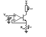
View attachment 140022
But this circuit is depended on Rset resistance and it will not act a "true constant current source". Because when you call it as "Constant Current Source" it should provide a constant current independent from load resistance.
This is better approximation form Linear.
https://www.linear.com/product/LT3092
 
Last edited:

Hi,

But this circuit is depended on Rset resistance and it will not act a "true constant current source". Because when you call it as "Constant Current Source" it should provide a constant current independent from load resistance.
The circuit isn't bad.
True, it is no current source, it is a current sink.
Load is where I_load is marked, in the upper path. And load current is independent of load resistor.
R_Set is fix.

Klaus
 

Current source versus sink is a possible distinction of both circuits. But usually, both are designated current source. The mirrored Linear circuit is better if and only if you have a ground referred load.
 

Hi
I think you can build a raw current source with a BJT and some resistor, if you know the load resistance.
 

Hi,

Hi
I think you can build a raw current source with a BJT and some resistor, if you know the load resistance.
Maybe you should give some additional information HOW to do it.

I personally doubt it.

Klaus
 

Hi, Klaus
I'm sorry! It's not "a BJT and some resistor", it's "a N JET and a resistor".


That is a thing called constant current diode. Or you can make a constant current source using saturation mode of JFET and D MOSFET: " In the saturation mode, a MOSFET's source-drain current is (ideally) independent of the source-drain voltage ".
 

Status
Not open for further replies.

Part and Inventory Search

Welcome to EDABoard.com

Sponsor

Back
Top