Continue to Site

Welcome to EDAboard.com

Welcome to our site! EDAboard.com is an international Electronics Discussion Forum focused on EDA software, circuits, schematics, books, theory, papers, asic, pld, 8051, DSP, Network, RF, Analog Design, PCB, Service Manuals... and a whole lot more! To participate you need to register. Registration is free. Click here to register now.

Video input on small TV modulator

Status
Not open for further replies.

neazoi

Advanced Member level 6
Joined
Jan 5, 2008
Messages
4,122
Helped
13
Reputation
26
Reaction score
15
Trophy points
1,318
Location
Greece
Activity points
36,951
Hi, I am trying to find the best way to feed the video into a small video modulator.
One way is this one http://electronics-diy.com/electronic_schematic.php?id=889 and another way is this one http://danyk.cz/tvvys_en.html
Which way is it better and leads to more stable operation?
I do not understand what is the purpose of the diode and if the DC blocking capacitor is better to be there, or whether direct coupling (like the first circuit) is better. Isn't direct coupling affect the bias as well, so that it leads to more unstable operation?
 
Last edited:
Both are poor designs but will work to some degree. Frequency stability will be very poor and the antenna/proximity will detune them

The first one doesn't have a constant input impedance, in fact it goes down to almost zero with the potentiometer set to ground.
The second is slightly betting that respect but has no DC restoration so it may drift with video content.

The idea of the diode/capacitor is that is charges the capacitor up to peak video voltage. A composite video waveform has sync pulses at constant amplitude so it helps to establish a DC baseline for the video. The technical term is "DC restoration". Without it, the bias conditions on the transistor would change according to average video level and that could cause distortion and/or frequency shift.

If I had to choose between them, the second would probably work better but a hybrid of the base circuit of the second with the DC restorer of the first would be an improvement. Do use a suitable transistor, the ones suggested in the first article are not really good for UHF work.

Brian.
 
  • Like
Reactions: neazoi

    neazoi

    Points: 2
    Helpful Answer Positive Rating
If I had to choose between them, the second would probably work better but a hybrid of the base circuit of the second with the DC restorer of the first would be an improvement.
Brian.

Can you help me a bit on that, how to make this improvement?
I have currently made the second circuit with the bfr91a. The only change, is that I use 3.3pF instead of 2pf and a 0.5-8pF variable capacitor in the LC. I intend to build a small amplifier after it, so it might be a better idea to modulate at the amplifier stage instead.
 
Last edited:

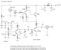
For better results the circuit need separated stages for the AM video modulator and for the RF oscillator:


[found at: www .qsl .net /va3iul /Homebrew _RF _Circuit _Design _Ideas /AM_ TV_ Transmitter .gifl]
 
Last edited by a moderator:
  • Like
Reactions: neazoi

    neazoi

    Points: 2
    Helpful Answer Positive Rating
Thats a better design but has a serious video impedance mismatch (should be 75 Ohms not 5k) and the video level control also adjusts the static RF output level.

With very few changes you can combine the design here: http://www.atv-projects.com/AM_Modulator.html with vfone's diagram and fix both those problems. Just connect point 'D' to ground and 'C' to +9V then remove the components above L2 and connect to point 'E' instead. That gives you independent bias control and video level control and some DC restoration as well. You can use a smaller transistor for TR2 as the original was for modulating at much higher current.

Brian.
 
  • Like
Reactions: neazoi

    neazoi

    Points: 2
    Helpful Answer Positive Rating
All of those circuits may modulate the video signal ( FBAS ) in somehow but there is no control over modulation depth,black level clamping and tracking,no audio modulation,no RF level control etc.
Therefore If I were you I'd think a integrated solution such as TDA8822T.Also, all these modulators have Double Side-Band modulators and carrier is not suppressed and their harmonics are pretty high to disturb the input LNA of the TV tuner..Especially I'm so surprised when I see C-Class amplifier and collector modulation.It ought really be quite a poor design.No sense at all..
So long time ago, I designed a Single-Side-Band Modulator for Satellite Head-End equipments and I know the potential issues and troubles.
Of course mine was a professional design but if you would see a reasonable result, you pay the invoice..
 

Yes, this is true. Class C amplifier cannot be used as an AM modulated stage. Unless you are using Envelope Tracking approach, which is used now by most of the 3G and 4G power amplifiers.
The link to the schematic that I posted is just for information, to see how looks a simple AM video modulator with separate stages.
Perhaps if you bias the modulated RF stage to Class A (or even AB) and add a better output impedance matching to the antenna, the circuit will work just fine.
 
  • Like
Reactions: neazoi

    neazoi

    Points: 2
    Helpful Answer Positive Rating
It clearly does work but I agree it isn't the best approach. In such a simple design, bearing in mind this started as a single transistor, there have to be compromises. Modulating the collector current WILL change the output of a class C amplifier, it may not be linear but then changing the bias of an unbuffered oscillator is probably a far worse crime!

Early TV modulator modules used a different approach, they ran a single transistor oscillator, a buffer stage then coupled the output through back-to-back diodes with the modulation fed at the junction. Ordinary silicon diodes were used with the video signal used to modulate the current flowing through them. It was a crude voltage controlled attenuator network, akin but not identical to the way more modern PIN switches work.

Brian.
 
  • Like
Reactions: neazoi

    neazoi

    Points: 2
    Helpful Answer Positive Rating
It clearly does work but I agree it isn't the best approach. In such a simple design, bearing in mind this started as a single transistor, there have to be compromises. Modulating the collector current WILL change the output of a class C amplifier, it may not be linear but then changing the bias of an unbuffered oscillator is probably a far worse crime!

Early TV modulator modules used a different approach, they ran a single transistor oscillator, a buffer stage then coupled the output through back-to-back diodes with the modulation fed at the junction. Ordinary silicon diodes were used with the video signal used to modulate the current flowing through them. It was a crude voltage controlled attenuator network, akin but not identical to the way more modern PIN switches work.

Brian.

This is exactly how this works **broken link removed**
Do you think it is a better approach, always talking in simple terms?
 

I would say yes, and as long as the PCB was built as shown, it should be reasonably stable.

It isn't quite the same method of modulation as used in early modules but the outcome is the same. This one shunts the signal with the diodes resistance, the older modules used two series diodes. This one is simpler, which gives best results would have to be found by experimentation.

Note to comply with normal video standards, P1 should have a resistor of 75 Ohms in parallel with its track (across the video input socket).

Brian.

This is interesting, a single diode performs better than a transistor :)
For simplicity I might make a second version with capacitive coupling of the LO to the diode, using maybe a small value capacitor and low LO level. could it work?

Also, I am thinking that a separate FM oscillator at UHF might be a better idea instead of mixing the 5.5MHz FM with the UHF modulator. This is because:
1. The UHF FM modulator works independently from the AM, so class C amplifiers can be used (more power )
2. The FM system does not affect the AM signal quality that way.
3. No 5.5MHz transformer needed (a bit hard to find).
4. The output TV signal will not suffer from the FM image, since there is no mixing involved.
 

This is interesting, a single diode performs better than a transistor :)
Only in the sense that it is used to reduce the level of RF from the oscillator. The transistor method changes the amount by which you amplify the signal so the overall output would be much higher.

For simplicity I might make a second version with capacitive coupling of the LO to the diode, using maybe a small value capacitor and low LO level. could it work?
Yes, but the reason for doing it that way is to minimize the effect the diode load has on the frequency. Adding a capacitor will negate the advantage.

1. Class C in this application is only used to simplify the circuit by eliminating the components needed for biasing the amplifier, it doesn't produce more power.
2. The FM injection level is very small (~ -18dB) compared with the video so it makes virtually no difference.
3. A tuned circuit at 5.5MHz is exceptionally easy to make!
4. Not strictly true but the reason isn't immediately obvious. You have to consider what happens in the TV receiver, they don't have two tuners tracking 5.5MHz apart with one for video and one for sound. They use a single tuner and wide IF bandwidth (>5.5MHz so both carriers and sidebands get through) and then an AM demodulator. The demodulated signal contains both the video modulation and the low level 5.5MHz sub-carrier which are then split. Typically, the signal goes to a tuned 5.5MHz IF amplifier to restore it's level then an FM demodulator to recover the sound, it also goes to an LPF to remove anything above say 5MHz so the sound sub-carrier is removed then on to the video processing stages. Now consider what happens if your transmitter oscillators are not EXACTLY 5.5MHZ apart, the resulting demodulated sound IF in the receiver will not
be at 5.5MHz and will not pass through the IF filter. There is also a risk that if the oscillators are less then 5.5MHz apart they will either enter the color processing circuits or show as patterning on the picture. Building a stable UHF oscillator without frequency lock is hard enough, building two of them with fixed difference would be a nightmare.

Also think of how the receiver creates the sound IF. It recovers it from the beat between the video carrier and the sideband 5.5MHz away. To be able to do that, both carriers must be present all the time. The sound carrier isn't a problem because the 5.5MHz is coming from an oscillator with fairly constant output level but the video is amplitude modulated so it's level is changing according to the picture content. It means that in order to keep the sound working you have to use less than 100% AM modulation level so there is always residual carrier present. I'm not sure what the target is in commercial TV applications but I think it's about 75%.

Brian.
 

1. The UHF FM modulator works independently from the AM, so class C amplifiers can be used (more power )

It's wrong.You have to combine 5.5 MHz Frequency Modulated Sound Carrier onto Base-band Video signal to obtain Composite Video signal.C-Class amplifier is not used to obtain more power, it's got Power Amplifier Efficieny superiority over
Class-A with cost of needing huge driving level and lot of harmonics.Changing collector voltage of a C-Class amplifier can somehow give you an Amplitude Modulation but you will get lot of troubles due to shifting of Operating Point.
 

Status
Not open for further replies.

Part and Inventory Search

Welcome to EDABoard.com

Sponsor

Back
Top