Continue to Site

Welcome to EDAboard.com

Welcome to our site! EDAboard.com is an international Electronics Discussion Forum focused on EDA software, circuits, schematics, books, theory, papers, asic, pld, 8051, DSP, Network, RF, Analog Design, PCB, Service Manuals... and a whole lot more! To participate you need to register. Registration is free. Click here to register now.

[SOLVED] PIC16F877 UART rx is not working TX and ADC are working

Status
Not open for further replies.

asthra123

Member level 1
Joined
Jul 2, 2013
Messages
32
Helped
1
Reputation
2
Reaction score
1
Trophy points
1,288
Activity points
1,582
Hello everybody
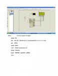
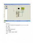
I am trying to show the ADC value and UART RX value on LCD .ADC value is showing on but the the uart value is not getting.
Please help me to find out the problem in my assembly code with (PIC16F877A) uart rx (receive ) (RXPOLL) . But the UART TX (TXPOLL) is working very well .
Please note the attached ASM code and screen shots of Proteus simulation...
 

Attachments

  • proteus-simulation2.jpg
    proteus-simulation2.jpg
    194.9 KB · Views: 111
  • proteus-simulation1.jpg
    proteus-simulation1.jpg
    198.1 KB · Views: 118
  • adc and uart.txt
    19.8 KB · Views: 102

Before even looking at the problem, tell me why you are redefining all the PIC register addresses and mixing 'banksel' directives with direct bank selection instructions.

You also state the PC should run at 19200 Bauds but the comment in the code suggest you configure the UART for 2400 Bauds.

Why are you polling the interrupt flag? It's much easier to enable interrupts and read the UART inside an ISR.

Brian.
 
dear sir....

sorry for the mistake ... actually I change the baud rate to 9600 . but I forget to change the comments .
I am using polling because I am not an expert with ISR method
 

I assume you are using MPLAB or MPLABX, can you post the project files please so I can replicate exactly what you have there. With just the source file it's difficult to know the environment you are using and it can make a big difference to the way the code works.

Brian.
 

dear sir...
please note the attached files
 

Attachments

  • adc and uart.rar
    24.2 KB · Views: 71

I am also attaching proteus simulation files
 

Attachments

  • temp lcd with uart proteus sim.rar
    62.6 KB · Views: 118

Dear all .....
still the same problem , anybody help to add an ISR ?
 

Sorry for the delay, I've been busy with other tasks.
I had some problems importing your code into MPLABX but I have it there now. It will take me a while to work out exactly what it does, especially the math part.

An ISR is quite easy to implement, based on your code, all you have to do is make room for the ISR code because it has to be located at address 0004 and you already have code there, then write the interrupt handler, the code for this is in the template, add the specific part to detect the UART as the cause of the interrupt and read the data and finally, have a mechanism to tell the main code that a character has been received.

What should happen is your main code loop runs all the time and when a character arrives, no matter when it is, the loop is suspended, the UART read then the loop resumes. It means it no longer has to wait in a loop checking the RCIF bit until a character arrives.

I'll try to add an ISR to your code and post it here as quickly as possible but I'm very busy at the moment so please be patient.

Brian.
 
I'm not at an assembler at the moment but I can see some errors.
Code:
IntSRV                       ;The result is placed in W register
     MOVWF          W_TEMP          ;Copy W to TEMP register
     SWAPF          STATUS,W        ;Swap status to be saved into W
     CLRF           STATUS          ;bank 0, regardless of current bank, Clears IRP,RP1,RP0
     MOVWF          STATUS_TEMP     ;Save status to bank zero STATUS_TEMP register
     MOVF           PCLATH, W       ;Only required if using pages 1, 2 and/or 3
     MOVWF          PCLATH_TEMP     ;Save PCLATH into W
     CLRF           PCLATH          ;Page zero, regardless of current page [COLOR="#FF0000"]<-- instead use banksel RCSTA to access CREN[/COLOR]
     BSF            RCSTA,CREN [COLOR="#FF0000"]<-- this should be in the register initialization not in the ISR[/COLOR]
     banksel        PIR1
RXPOLL btfss          PIR1, RCIF    ;RX Buffer Full? (i.e. Data Received?)
     goto           RXPOLL [COLOR="#FF0000"]<-- remove this line, if the interrupt occurred RCIF must already be set[/COLOR]
     banksel        RCREG
     movf           RCREG,0 ;received data to W
     banksel        TEMPLOW
     movwf          TEMPLOW   ;tempHIGH <--ADRESH
     MOVF           PCLATH_TEMP, W    ;Restore PCLATH
     MOVWF          PCLATH            ;Move W into PCLATH
     SWAPF          STATUS_TEMP,W     ;Swap STATUS_TEMP register into W
;(sets bank to original state)
     MOVWF          STATUS            ;Move W into STATUS register
     SWAPF          W_TEMP,F          ;Swap W_TEMP
     SWAPF          W_TEMP,W          ;Swap W_TEMP into W
     retfie

I would move all that code so it is 'in line' with the interrupt vector like this:
Code:
;=========================================================
    org       0x0000
    GOTO      START
    org       0x04                   ;        
    goto      IntSRV                 ;added isr [COLOR="#FF0000"]<-- put the whole ISR code here[/COLOR]
    org       0x10  [COLOR="#FF0000"]<-- remove this line otherwise you may be overwriting the end of the ISR code[/COLOR]

The "START" label will make sure the address of the 'GOTO START' is correct. The assembler learns the addresses of all the labels on it's first pass then inserts them into the instruction on the second pass so except for special cases such as the ISR and sometimes data tables, you don't need to use 'org' again. When you add an 'org' statement it resets the address where the following instructions will be located so there is a risk of overwriting something already there, it's better to let the assembler work out the best addresses for you. You DO need to use 'org' at the reset vector (0x0000) and the ISR (0x0004) as they are special addresses and the code following them has to be there because of the way the PIC works internally.

Brian.
 
Dear sir,
thank you for your quick reply. I have changed the code and now the code is running . . but the 2nd row of the received data on lcd display is incorrect (1st row showing the ADC value is correct).View attachment CHANGED CODE.txt
 
Last edited:

Dear all.....
The main code have a subroutine "AGAIN " (maths routine) to show the ADC value on LCD display.
like that the ISR for UART receive also required the subroutine to show the received value on the second line of the LCD screen
how we can implement the code .
 

dear sir....
My question is the ASM code for PIC16F877 have to display both ADC value and UART value on LCD by two lines..
The main code have two subroutines one for ADC and other for LCD write . but i am using an ISR for reading UART receive , and how we show the UART receive value on the second row of the LCD. can we use the lcd write subroutine in the main loop ?
 

Hi,

Within the Uart_receive_ISR just put the received data in a buffer (FIFO) and set a flag to indicate new received data.
Don't process the data in the ISR. Every ISR should be short in time.
In main loop: Poll the flag, if SET process the received data. Send them to the display as you like.

Don't mix display access in main_loop and ISR.
Either do all display access via ISR, or all display access in main

Klaus
 
Thank you very much sir..
I can solve the problem with your help..
now its working..
 

Status
Not open for further replies.

Similar threads

Part and Inventory Search

Welcome to EDABoard.com

Sponsor

Back
Top