Continue to Site

Welcome to EDAboard.com

Welcome to our site! EDAboard.com is an international Electronics Discussion Forum focused on EDA software, circuits, schematics, books, theory, papers, asic, pld, 8051, DSP, Network, RF, Analog Design, PCB, Service Manuals... and a whole lot more! To participate you need to register. Registration is free. Click here to register now.

Tricky nodal analysis

Status
Not open for further replies.

cartman007

Member level 2
Joined
Nov 13, 2012
Messages
45
Helped
0
Reputation
0
Reaction score
0
Trophy points
1,286
Activity points
1,638
Hi everyone.

Q2.png

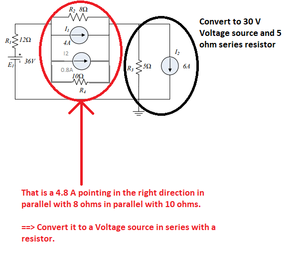
I need help trying to figure out what to do with the first branch of this circuit.

I am not sure if a super node could be used?

Here is an example of the nodes I think I should have in RED.
I am not quite sure if I am to use a SuperNode on the little part in the blue circle.

Q2mesh.png

Thanks
 

No, you forgot to consider the node between E2 and R4 inside blue circle. You could alternativelly replace both components by another current source and resistor, both in parallel with the other ones already there, which would certainly simplify the analysis by reducing the nodal matrix size.
 

Could you maybe show me what you mean?
 

How does this look... I find it awkward to simply convert it without taking other sources etc into consideration?

Q2.png
 

I did not check if you made the correct calculations, but it is exactly what I was talking about.

- - - Updated - - -

Another tip: Why don't you convert the remaining voltage source/series resistence to the same Northon circuit ? This way, the source of the matrix vector would have just current, instead of a mix of current and voltage sources.
 

....
Here is an example of the nodes I think I should have in RED.
I am not quite sure if I am to use a SuperNode on the little part in the blue circle.

View attachment 139912

Thanks

Just write the node equations following the rules:

(1/R1+1/R2+1/R4)V1 - (1/R2+1/R4)V2 = E1/R1 - E2/R4 - I1
-(1/R2+1/R4)V1 + (1/R2+1/R3+1/R4)V2 = E2/R4 + I1 - I2​
 

So I drew another diagram and I palced the nodes. Do they look ok?

I am not quite sure on how to go about doing this specific SuperNode though.

Ok soo this is what I came up with ->
**broken link removed**

I just dont get how I will go about SUPERNoding this circuit at all?

Thanks
 

I'm unaware of the specific term "SUPERNoding".
The only thing you have to do now is to perform the Norton analysis.
 

The circuit can be solved in 10 seconds.
Starting from the circuit in post #5, see picture below.


You will have 1 mesh with voltage sources and resistors. Pretty easy to solve.

- - - Updated - - -

How does this look... I find it awkward to simply convert it without taking other sources etc into consideration?
That is called Source Transformation which is a direct application of Thevenin/Norton theorem.
https://en.wikipedia.org/wiki/Source_transformation

- - - Updated - - -

I am not quite sure on how to go about doing this specific SuperNode though.
There is no SuperNode here.
 

Status
Not open for further replies.

Similar threads

Part and Inventory Search

Welcome to EDABoard.com

Sponsor

Back
Top