Continue to Site

Welcome to EDAboard.com

Welcome to our site! EDAboard.com is an international Electronics Discussion Forum focused on EDA software, circuits, schematics, books, theory, papers, asic, pld, 8051, DSP, Network, RF, Analog Design, PCB, Service Manuals... and a whole lot more! To participate you need to register. Registration is free. Click here to register now.

gain of amplifier used in filter

Status
Not open for further replies.

simplsoft

Full Member level 2
Joined
Nov 24, 2014
Messages
127
Helped
0
Reputation
0
Reaction score
0
Trophy points
16
Activity points
1,045
Hello

I want to know if I design a OTA(operational transconductance maplifier) let suppose of 70dBgain but when usig the OTA in designing a filter the close loop gain of the filter is 0dB ideally practically -6dB as shown in the attached figure. Then what is the reason behind to get such high gain when the filter designed using that OTA is 0dB. OTA-C filter.jpg
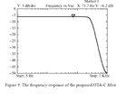
 

... Then what is the reason behind to get such high gain when the filter designed using that OTA is 0dB.

(Non-)accuracy or non-linearity (in first order consideration) = closed-loop-gain/open-loop-gain .
 

If it's an active filter, it depends upon feedback to obtain the desired response and any deviation from an ideal amp will make the response less than predicted by the filter equations (which assume an ideal amp with infinite open-loop gain and frequency response).

So you thus want the amp to have a high open loop gain and frequency response so that the filter response approaches the ideal.
 

Status
Not open for further replies.

Similar threads

Part and Inventory Search

Welcome to EDABoard.com

Sponsor

Back
Top