Continue to Site

Welcome to EDAboard.com

Welcome to our site! EDAboard.com is an international Electronics Discussion Forum focused on EDA software, circuits, schematics, books, theory, papers, asic, pld, 8051, DSP, Network, RF, Analog Design, PCB, Service Manuals... and a whole lot more! To participate you need to register. Registration is free. Click here to register now.

Design capturing range 350Hz-550Hz by using Hef4046b PLL

Status
Not open for further replies.
Hello,
Working 24hr per day make micro controller(Whole time fft has to be done) over heat. Because of that reason only i'm using PLL to trigger micro controller when it captures signals inside pass band. Here still i haven't checked. Im still at the stage of selecting values for resistor and capacitors.
Please help me to find values. It will be a great help
 

Hi,

Working 24hr per day make micro controller(Whole time fft has to be done) over heat.
This is nonsense. Any microcontroller is made for working 24/7 without overheat.
And doing an FFT mabe takes 20ms of processing power.
Performing a "wait_ms (20)" will need the same processing power.
A microcontroller does not care about what it has to do...
Waiting 24 hours for you to press a key is the same as performing 24hours one FFT after the other.

Klaus
 
Hi,
What your telling was true. earlier i thought to record them on a sd card. Later fft will be done. when pll detects presence of mosquito it will trigger micro controller and start to record it on sd card. Its point less right? Also inside my Micro-controller dsp filtering also happens
 

Does anybody know what is a typical speed of flight for a mosquito? Maybe a Doppler effect must be considered -- and for that purpose the 2nd order loop filter is not able to track reference frequency (mosquito buzzz).
 

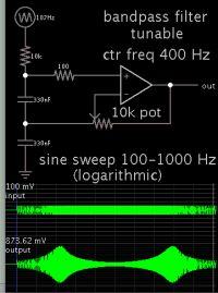
You can expect to need extreme amplification at a mic detecting mosquitoes. But then you also amplify unwanted noises (at low and high frequencies). Therefore it's wise to filter your initial signal through a bandpass in an early stage.

Example, this filter combines the two functions. It is not too complex. You can adjust the rolloff curve as well as gain. You need to select capacitor values to obtain a desired center frequency.


It assumes an input resistance of 10k for the mic.
 
@BradtheRad, Yes that's true. Noise also gets amplified. I order Automatic gain control mic and amp. refer to below datasheet. Seems like its pretty handy for my project.

https://cdn-learn.adafruit.com/downloads/pdf/adafruit-agc-electret-microphone-amplifier-max9814.pdf

Also below pdf explain more

https://datasheets.maximintegrated.com/en/ds/MAX9814.pdf

It can pick higher Vrms value and has automatic gain control ability. What i was thought to do is Output signal comes out from the Mic Amp pass through a Low pass filter(Cut off = 1800Hz). Since i need to pick the 3rd harmonic also(for fft inside the Micro controller going check 3rd harmonic values also). The filtered output is pass through the pll. From that PLL can capture fundamental and trigger mcu. When sampling happening at MCU, by using a IIR band pass filter again noise will be cancel. So before fft 100% there's no noise. FFT readings will be more accurate)

- - - Updated - - -

Also i thought to connect Low pass out for both PLL input and ADC input as below figure.

20170709_115759.jpg

Is that possible to connect single out put line for both inputs in the case of microphone signal???
 
Last edited:

Status
Not open for further replies.

Similar threads

Part and Inventory Search

Welcome to EDABoard.com

Sponsor

Back
Top