af19
Newbie level 4
Hello.
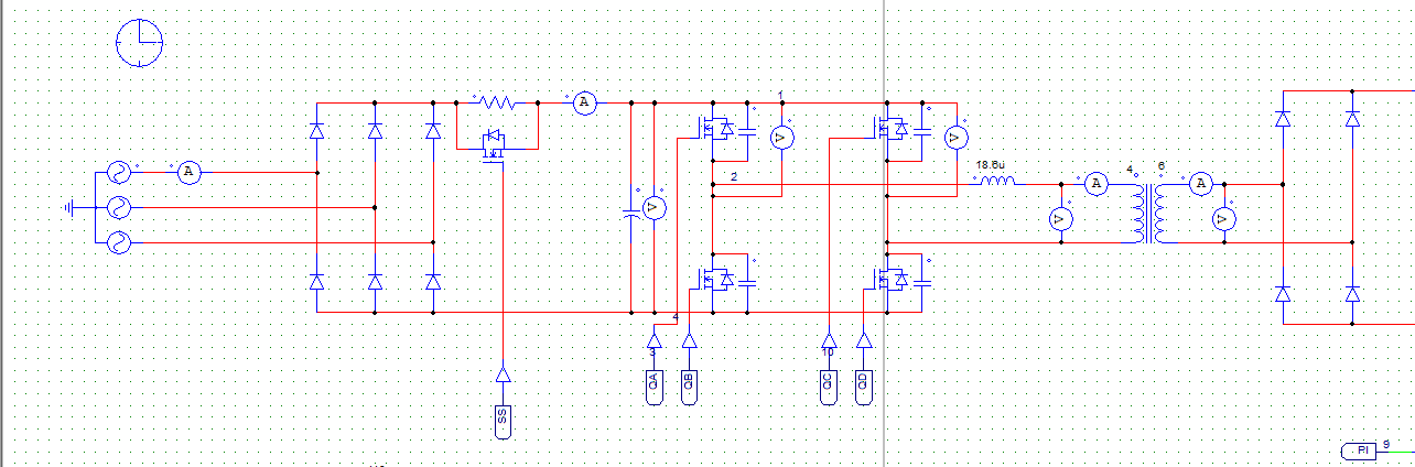
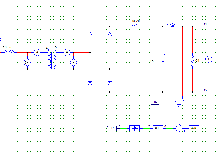
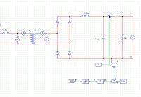
I simulated a zvs full bridge in psim with below specs
Vin: 280 VDC (6 pulse rectifier).
Vout: 270 VDC
Iout:5 A
Switching Transformer: 4:6 ratio.
Inductor for ZVS: 18.6 uH.
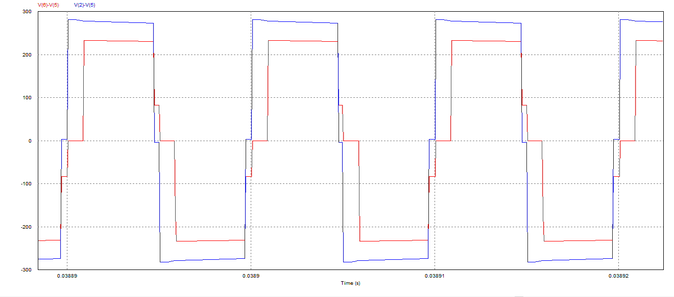
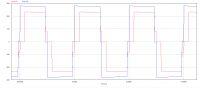
My problem is that I have a very large voltage drop after the ZVS inductor and my square wave shape changes after this inductor. I tought inductor should be a loss-less element. May
The circuit schematics and the voltage before and after the inductor are attached.
The blue figure is before the inductor and the red figure is after the inductor.
Can anyone tell me why I have this voltage drop across the inductor? and why does the voltage shape changes?
Thanks.
I simulated a zvs full bridge in psim with below specs
Vin: 280 VDC (6 pulse rectifier).
Vout: 270 VDC
Iout:5 A
Switching Transformer: 4:6 ratio.
Inductor for ZVS: 18.6 uH.
My problem is that I have a very large voltage drop after the ZVS inductor and my square wave shape changes after this inductor. I tought inductor should be a loss-less element. May
The circuit schematics and the voltage before and after the inductor are attached.
The blue figure is before the inductor and the red figure is after the inductor.
Can anyone tell me why I have this voltage drop across the inductor? and why does the voltage shape changes?
Thanks.