Continue to Site

Welcome to EDAboard.com

Welcome to our site! EDAboard.com is an international Electronics Discussion Forum focused on EDA software, circuits, schematics, books, theory, papers, asic, pld, 8051, DSP, Network, RF, Analog Design, PCB, Service Manuals... and a whole lot more! To participate you need to register. Registration is free. Click here to register now.

how to connect 2*16 LCD with STM32 microcontroller

Status
Not open for further replies.

farhang_760

Newbie level 6
Joined
Mar 8, 2015
Messages
12
Helped
0
Reputation
0
Reaction score
0
Trophy points
1
Activity points
107
Hi, I want to connect 2*16 LCD (with +5v logic) with STM32 (e.g. f030) microcontroller, as you know the GPIO output voltage is 3.3V. i found a schematic as you see below:
image_2017-06-18_10-34-24.png
you see that except +5V power port all of them pull up with external resistor. is it correct? i heard from someone that we could connect them directly to stm32 without any pullup resistor,is it works?
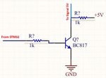
another way is using BJT to connect 3.3v gpio to 5v signal whats your idea?
BJT.JPG
 

Hi,

i heard from someone that we could connect them directly to stm32 without any pullup resistor,is it works?
This is a frequently asked question...with a lot of useful answers and example circuits...
--> simply do a forum search.

General rule:
One device outputs the signals. The HIGH and LOW output signal levels are specified in it's datasheet. Look for V_OH and V_OL.
The other device is the input. The valid input levels are specified in it's datasheet. Look for V_IH and V_IL.
Check if input and output levels soecifications meet.

Klaus
 

Hi,


This is a frequently asked question...with a lot of useful answers and example circuits...
--> simply do a forum search.

General rule:
One device outputs the signals. The HIGH and LOW output signal levels are specified in it's datasheet. Look for V_OH and V_OL.
The other device is the input. The valid input levels are specified in it's datasheet. Look for V_IH and V_IL.
Check if input and output levels soecifications meet.

Klaus

thanks Klaus, first, I search in forum but cant find any useful data and then post this topic, maybe i dont choose good keywords!
I see the LCD Doc and it says it input works 4to5 volt but as i said somone told me that it works with 3.3v, this is the reason that i ask this question here to use from users experiences.
if you know what keyword should i search, please tell me. thanks alot
 

Option:
1. Connect directly and belive that it will work. (my choice, it works)
2. Connect directly and configure pins as OD (open drain), use pull up resistors to 5V (choose 5V tolerant pins)
3. Use level shifter IC (stupid way, it is made for 1.8v <-> 3.3v and to 5.0v shifting, 3.3v <-> 5.0v normally not use, if IO is 5v tolerant)
 

Status
Not open for further replies.

Similar threads

Part and Inventory Search

Welcome to EDABoard.com

Sponsor

Back
Top