Continue to Site

Welcome to EDAboard.com

Welcome to our site! EDAboard.com is an international Electronics Discussion Forum focused on EDA software, circuits, schematics, books, theory, papers, asic, pld, 8051, DSP, Network, RF, Analog Design, PCB, Service Manuals... and a whole lot more! To participate you need to register. Registration is free. Click here to register now.

using Audio amp as a power inverter

Status
Not open for further replies.

Enzy

Advanced Member level 1
Joined
Mar 20, 2016
Messages
488
Helped
2
Reputation
4
Reaction score
2
Trophy points
18
Activity points
4,607
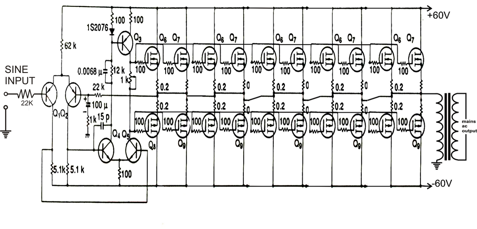
I made a few simple inverters and also simple amplifiers and I have noticed that audio amplifiers produce pure sinewave. OK now I realize that audio amplifiers clip when they are over driven (passing the supply voltage or current). If I am to use an audio amplifier as an inverter the best way I think to get high power would be to use several batteries in series to achieve a higher voltage.

But what if I want to use 1 12v battery but be able to pull high current from it?

The trick is normally the amplifier require a dual polarity input so I think 2 batteries would be needed to be connected in series and the point where the batteries are series would be the 0v rail.

Couldnt I build a circuit to convert a single supply into a dual polarity supply with high current output.

So the input of the amplifier could be supplied with a simple pure sinewave oscillator circuit ( I was thinking off a 555 circuit) im not a pro at any form of designs either amplifiers or inverters but I do tend to read about them often and what I tend to realize is that pure sinewave is easy to produce but it seems to be complex to amplify given my limited knowledge thats why I wanted to try this method of creating a simple circuit to send puresinewave signal to the input of an audio amplifier while using 1 12v battery and also still gain high power, I figire there will e efficiency issues but can anybody elaborate on this method.
 

First of all, you're not going to get a sinewave out if a 555. Secondly, this sounds like an extremely inefficient inverter. Third, you don't need 2 batteries to get a bipolar output, just a transformer.
 

First of all, you're not going to get a sinewave out if a 555. Secondly, this sounds like an extremely inefficient inverter. Third, you don't need 2 batteries to get a bipolar output, just a transformer.

I was not refering to any very precise pure sinewave circuit just a simple oscilator with an inductor to produce a wave looking like a pure sinewave with the Rms values to match that of a pure sinewave.

you said I dont need 2 batteries to get a bipolar output I need a transformer how would a transformer be implemented if the source of power is a battery.

in my example I have a 12v battery (which is a single rail supply) and I need it to power a circuit that needs a bipolar supply, if there is by chance a method that involves a transformer that would seem to me like a building a dc-dc converter which would involve a power inductor not sure if that is correct. If so that circuit wouldnt make sence I could just use the Ac output of the boost converter and a rectifier circuit then a circuit to converter high frequency to 50hz.

in my mind I am thinking that I can have a battery (12v) use some passive components (transistors ect) to create a bipolar supply of 12-0-12VDC which would be used to power the amplifier, in my case now I am not worrying about effieciency since im working with a theory, im moving in stages im at the point now which I am wondering if this idea can work.
 

A pure sinewave oscillator circuit is common and is simple.
A linear audio amplifier wastes a lot of power supply power by making heat, use a class-D modern audio amplifier instead that does not produce much heat.
Many audio amplifiers (including class-D efficient ones) are bridged and can drive a transformer. A single rail supply will be fine.
 

since its class D I guess I would have to purchase an amplifier or probably try building the one I was discussing with you but how will I use a single rail when it requires a dual rail supply?

- - - Updated - - -


this circuit is using pnp and npn transistors I would use P channel and N channel Fets that way I think I could use less ( I have some irfz44n and Irf4905 laying around) using those I should be able to use probably about 3 pairs to get 1000va or more.

At the part that says sine input I could use a 55 or even an opamp to generate a sinewaveI would really like to make class D amplifiers but that will be an issue for me at the moment I am reading up though.
 

These all are linear inverters, efficiency will be less than switch mode inverter. Why cant you try with standard driver module
**broken link removed**

Hope this post will be helpful to you!
 

These all are linear inverters, efficiency will be less than switch mode inverter. Why cant you try with standard driver module
**broken link removed**

Hope this post will be helpful to you!

thanks, I am aware of boards like these for almost every project I do, the thing is its my hobby to build circuits, I have always just build circuits in the past which alot of them tend to fail because circuits arent properly designed or they are just concepts I didnt go to school to designs circuits but im trying to build circuits these days as I think about them nothing I do is original and I get help to do what I do.

Its my way of teaching myself how to do things I just find projects and build circuits and by changing around the circuit I learn how each part works which probably makes no sense to most people here.

- - - Updated - - -

I tend to do a bit of repairs of electronic devices even if I need just 1 part I tend to buy atleast 10 of each mostly because I purchase form china and I very much prefer to build things more than repairing so I rather to build circuits than to buy them even when if its cheaper hence why I dont factor price in my posts I always try to ensure to use components I already have.
 

Hi,

since its class D I guess I would have to purchase an amplifier or probably try building the one I was discussing with you but how will I use a single rail when it requires a dual rail supply?
A bridged class D won't need dual rail supply.

Klaus
 

I did some reading and I have seen more than one method of bridging amplifiers I think some of what I have seen is incorrect though, however it seems to bridge an amplifier I would have to take 1 signal (mono) and send to both sides of the amplifier even though I realized that one side of the amplifier should be inverted and I realized that they sell off the shelf products for that purpose.

SO I would use the positive speaker outputs from both amplifiers and leave the negatives disconnected.

What I dont understand is how this would enable me to use a single rail supply or is it because one amplifier isnt required to do a push and pull of the speaker simultaneously then its not required, meaning when the positive output from one amp pushes then the other positive output from the other amplifier pulls.

How would I make such a connection since I would have to leave a rail disconnected, based on the example I shared in post #5 using a 12v battery I would connected +12v to where it says +60 and then I would connnect 0v to GND
 

It is easy to convert an opamp or audio amp circuit from a dual polarity supply to a single positive supply. Simply add input and output capacitors and bias the input at half the supply voltage.
Mosfets waste a lot of power making heat in your circuit because of their high gate-source voltage.

Texas Instruments make some excellent class-D audio amplifier ICs with a fairly high output power.

- - - Updated - - -

Most car radio amplifier ICs are bridged. Then the output voltage swing (and output current) are almost doubled for almost 4 times the power of a single amplifier using the same supply voltage. Since both amplifiers in the bridge have their outputs biased at half the supply voltage then an output coupling capacitor is not needed even though it has a single polarity power supply voltage.
 

Attachments

  • Mosfets audio amplifier.png
    Mosfets audio amplifier.png
    345.6 KB · Views: 327

I live in a 60Hz country.
One time where I had to test a design across the 48 to 62 Hz range, I used a spare audio power amplifier and a sinewave oscillator. The output voltage was not enough, thus I used a common steel core transformer wired backwards: the secondary to the amplifier, and the primary as the voltage output for the device under test.

As others have mentioned, it was very inefficient. But I required only about 25 watts for short periods of time.

Why would you say its inefficient, couldnt it be that you were using a inefficient inverter with an incorrectly rated transformer?

Why I ask is that if your load requirement was so low and yet you still noticed that the amplifier was inefficient then to me either you were testing for efficiency or it was very evident that you had voltage drops or heating wouldnt that just come down to you not having the correct size amplifier for the task?

What is the difference between for example a 1000w amplifier (class D) and a 1000w Pure sinewave inverter?

- - - Updated - - -

It is easy to convert an opamp or audio amp circuit from a dual polarity supply to a single positive supply. Simply add input and output capacitors and bias the input at half the supply voltage.
Mosfets waste a lot of power making heat in your circuit because of their high gate-source voltage.

Texas Instruments make some excellent class-D audio amplifier ICs with a fairly high output power.

- - - Updated - - -

I saw that you made the supply 120vdc or should it be 12vdc?

you explained in another post how FET's waste more power but why is it that most circuits tend to be using FET's instead of transistors? in my case I see where I could possibly use 2 pairs of Fet's to gain the same power as 10 pairs of transistors would the only benefit to that be cost?

As for bridging a class D amplifier it doesnt seem like it will work if I buy those cheap chinese amplifiers as I wont be able to make the changes you made above, so amplifiers I purchase would have to be designed to be bridged.
 

Please read my post. I never mentioned it was a class D amp.

All that I was saying was that audio amps may be used as a spare inverter in certain specific cases.
 

Why would you say its inefficient, couldnt it be that you were using a inefficient inverter with an incorrectly rated transformer?
He must have used a linear audio amplifier that wastes about 50% of its power supply power producing heat, instead of a class-D switching amplifier that heats with only 10% of its power supply power.

Class-D amplifiers and switched-mode pure sinewave inverters both use Pulse-Width-Modulation at a high frequency then an output filter. The output transistors switch fully on and fully off. When fully on then there is only a small voltage across the transistor producing low heating and when fully off then the current in the transistor is zero so there is no heating. A linear amplifier has voltage across the output transistors and current in them all the time producing lots of heat when loaded and the output swing is high.

Because the switching frequency in a pure sinewave inverter is high then a small lightweight transformer can be used. The modulation frequency is 50Hz or 60Hz.

- - - Updated - - -

Enzy, you showed a high power audio amplifier that used a +60V and -60V (120V total) supply so I converted it to a +120V supply. The transformer simply stepped up the output voltage from its maximum of 100V p-p to the 340V p-p of a 120V AC sinewave.
It is a linear amplifier producing lots of heat, not a cool class-D switching amplifier. Mosfets cannot be used as source followers like that when the supply voltage is low because a Mosfet needs up to 10V from its gate input to its source output to be fully turned on so a 20V supply will produce a very low output voltage swing. Ordinary power transistors have a base-emitter voltage of about 1V so with a 12V supply the complementary emitter followers produce an output voltage swing of about 10V p-p.

A switching Mosfet has its load at its drain pin (not at its source pin) so that it can fully turn on when its gate voltage is 10V.
 

Please read my post. I never mentioned it was a class D amp.

All that I was saying was that audio amps may be used as a spare inverter in certain specific cases.

I figured you weren't using a class D amp thats why I said what I said, I said probably you were using an inefficient inverter and not a class D in other words, read again.

- - - Updated - - -

\


- - - Updated - - -

Enzy, you showed a high power audio amplifier that used a +60V and -60V (120V total) supply so I converted it to a +120V supply. The transformer simply stepped up the output voltage from its maximum of 100V p-p to the 340V p-p of a 120V AC sinewave.

Ill have to redraw the diagram to show the voltages I want but as I said in the orignal post I plan to only use a single 12v battery so the source will only be 12v.

- - - Updated - - -

which would probably enable me to use a 0-12v transformer on the output of the amplifier

- - - Updated - - -

A switching Mosfet has its load at its drain pin (not at its source pin) so that it can fully turn on when its gate voltage is 10V.

What about digital FET's that turn on fully at 5v
 

A linear audio amplifier uses the output Mosfets as source followers so the output is much less (10V for most Mosfets or 5V for logic level Mosfets) then with a 12V supply the output voltage swing will ne nothing or will be about 2V.
When the supply is higher than 10V then you do not need logic level (5V) Mosfets in a switching class-D amplifier or inverter.
 

Well I currently I dont have a class D amplifier I can build the one in this post I assume is a class AB? which is linear I have 4 pairs of tip135 and tip136 and I have about 4 pairs of irfz44n and irf405 which ones would you recommend using 12v battery supply with the circuit above and about what kinda power could I get from either FET's or transistors?

- - - Updated - - -

circuit prototype.png

I tried to complete the circuit
 

Why don't you understand that the Mosfets you show need a gate-source voltage of 10V to fully turn on? Then they will not work in your amplifier unless its supply voltage is much higher.
The output power will be almost nothing. If you use logic level (5V) Mosfets then the output voltage swing will be about 2V p-p and the power into a 4 ohm speaker will be about 0.1W.

If you use TIP135 and TIP136 darlington transistors the output power into a 4 ohm speaker will be 1.5W.
If you use ordinary transistors then the output power will be 3W.
 

Attachments

  • Mosfets output.png
    Mosfets output.png
    14.8 KB · Views: 157

So I would actually need a boost converter circuit to use one battery, if not then I would need to series a couple batteries atleast 3 12v batteries

- - - Updated - - -

Do you think I can bridge 2 of these boards
Look at this on eBay https://www.ebay.com/itm/182307479849
 

The very cheap high power Chinese amplifier is an "assembled kit" and has no Name Brand. Are the spec's believable? Is it designed properly so that all parts are not overloaded? Is it assembled properly?
The ebay ad does not say but this amplifier might be class-D if the efficiency of 80% is true.

If you use an audio inverter for one amplifier then two amplifiers can be bridged but the load must not be less than 4 ohms and the power is almost doubled.
Three 12V batteries make 36V. This amplifier needs 150V.
 

Status
Not open for further replies.

Similar threads

Part and Inventory Search

Welcome to EDABoard.com

Sponsor

Back
Top