Continue to Site

Welcome to EDAboard.com

Welcome to our site! EDAboard.com is an international Electronics Discussion Forum focused on EDA software, circuits, schematics, books, theory, papers, asic, pld, 8051, DSP, Network, RF, Analog Design, PCB, Service Manuals... and a whole lot more! To participate you need to register. Registration is free. Click here to register now.

Digital Latch circuit for LED

Status
Not open for further replies.

eengr

Member level 4
Joined
Mar 9, 2016
Messages
75
Helped
0
Reputation
0
Reaction score
0
Trophy points
1,286
Activity points
4,270
Hi there
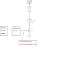
I am trying to build a circuit that turns a LED ON after 24 hours and then LED should stay ON after that. The solution needs to be without using any micro controller. I am planning to use a binary counter IC 4040 fed at Clock Input from a 555 timer. The Q12 output of 4040 would go HIGH after 24 hours for the configuration shown below in the block level diagram. This output will turn the NMOSFET and LED ON. The problem I have is that after next 24 hours this output would go LOW again for another 24 hours causing the LED to go OFF for another 24 hours. I would like to have some sort of latch at 4040 output that keeps this LED ON once 1st 24 hours are lapsed. I thought about using D type flip flop but this also requires Enable line and I am not sure how to control the Enable line in sync with this 24 hr output from 4040. Any help would be greatly appreciated.
555 Timer & 4040 are powered from same 3.3V rail as used for LED/resistor Digital Latch cct.jpg
 

If you can live with a small voltage drop across it, use an SCR instead of a FET. Once triggered the only way to turn it off is to cut the 3.3V feed.

Other ways:
1. add a flip-flop between the 4040 and the FET to latch the signal
2. if the 4040 doesn't drive anything else, wire it's output pin to the reset on the timer so it stops oscillating when the 4040 output goes high. (may need inversion)

Brian.
 
  • Like
Reactions: eengr

    eengr

    Points: 2
    Helpful Answer Positive Rating
Thanks for the feedback.

I think SCR might be the only way here.

If I reset the 4040 after my output goes HIGH so that 4040 stops counting/oscillating then it also toggles all the outputs to LOW as Resetting 4040 causes all outputs to go LOW --- (unless there is a way around it !?!)

If I use D - Type flip flop for instance then its CLK line needs to be in sync somehow with the Data Input. As Flipflop latches the input to output as long as CLK is held HIGH. Some how the CLK needs to go LOW after Output from 4040 goes HIGH (after 1st 24 hour lapse) so that it Flip flop does not change the output for next transition of Data Input (4040 output) from HIGH to LOW and I am struggling to get control of this CLK signal for flipflop!?!
 

If I reset the 4040 after my output goes HIGH so that 4040 stops counting/oscillating then it also toggles all the outputs to LOW as Resetting 4040 causes all outputs to go LOW --- (unless there is a way around it !?!)
You didn't read my post carefully! I said the reset on the timer so no further clock pulses go to the 4040 and it stays in the same state forever. This method does have the advantage that you CAN reset it if necessary with the 4040 reset pin. I can't remember if the 555 reset pin is active high or low so you might have to invert the signal to make it stop oscillating.
If I use D - Type flip flop for instance then its CLK line needs to be in sync somehow with the Data Input. As Flipflop latches the input to output as long as CLK is held HIGH. Some how the CLK needs to go LOW after Output from 4040 goes HIGH (after 1st 24 hour lapse) so that it Flip flop does not change the output for next transition of Data Input (4040 output) from HIGH to LOW and I am struggling to get control of this CLK signal for flipflop!?!
You already have the signal to do that. Feed to 4040 to the 'D' input and clock it from the output of the 555. It's Q will then follow the 4040 output within one 555 clock cycle. The other method is to tie 'D' high and clock it with the 4040. Don't forget there are other flip-flop types, for example you might be able to use an S-R configuration using two logic gates.

Brian.
 
  • Like
Reactions: eengr

    eengr

    Points: 2
    Helpful Answer Positive Rating
Thats a 4060 with its inverters forming an oscillator with an inhibit via D1. Eengr has a 4040 which requires an external clock so it wouldn't work.

Brian.
 

Thats a 4060 with its inverters forming an oscillator with an inhibit via D1. Eengr has a 4040 which requires an external clock so it wouldn't work.
He said he was "planning to use" a 4040 so I assumed that he was still in the planning stage and didn't have the actual parts yet.
 

Status
Not open for further replies.

Similar threads

Part and Inventory Search

Welcome to EDABoard.com

Sponsor

Back
Top