Continue to Site

Welcome to EDAboard.com

Welcome to our site! EDAboard.com is an international Electronics Discussion Forum focused on EDA software, circuits, schematics, books, theory, papers, asic, pld, 8051, DSP, Network, RF, Analog Design, PCB, Service Manuals... and a whole lot more! To participate you need to register. Registration is free. Click here to register now.

Embedded Track Inductance

Status
Not open for further replies.

HardwareChap

Junior Member level 1
Joined
May 7, 2015
Messages
17
Helped
0
Reputation
0
Reaction score
0
Trophy points
1,281
Activity points
1,445
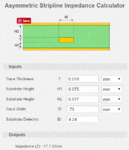
I'm trying to determine the inductance of a track embedded within a PCB to simulate its affect. The layer stack info is below as I've found plenty of tools to determine trace impedance:
Inductance Trace.GIF

The length of the track is 77 mm. How do I get from the stack info provided to an inductance that I could plug into LTSpice to simulate?
 

Better tools give you specific capacitance and inductance per length unit. Does the tool really display -17.7 ohm? Something's obviously wrong then.

I get 56 nH/m.
 

There are a few problems:

- The online calculator gives invalid results (negative ZL), most likely because the aspect ratio (line width / line thickness) is too extreme
- That very wide line has a lot of shunt capacitance, so treating it as a series inductance is inaccurate.

Line impedance of a lossless line is
ZL=sqrt(L'/C')

You can get the free Sonnet Lite EM solver and simulate the line as a flat (zero thickness) conductor, which is quite accurate at this width. Then, you can export a SPICE pi model (L + C).

I did a quick setup (model attached) and get ~ 7.6 Ohm line impedance.
Sonnet Lite model: View attachment sl.zip

A simple equivalent circuit with series L and shunt C is valid if the line length is less than 1/20 wavelength. For the line length of 10mm that I simulated, I get this equivalent circuit:

C_C1 1 0 3.991385pf
C_C2 2 0 3.993408pf
L_L1 1 2 0.590898nh

If the line is longer than 1/20 wavelength at your frequency of interest, you need to cascade multiple short segments (cascaded LC ladder network, optional R and G are conductor losses and dielectric losses).


Thanks for your replies FvM and Volker. Sonnet Lite looks really good, but the track I want to simulate isn't RF. It's the highlighted track below:

Trigger coil cct.GIF

The gate of the SCR will be driven by a micro and the trigger coil is a Tokyo Photoflash. There is concern that a track that is too long from the SCR to capacitor TC will be too inductive and the interaction of the parasitics would cause problems, so I'm just trying to get a feel for a realistic value to plug into Spice.
 

Sonnet Lite looks really good, but the track I want to simulate isn't RF.

Fast signals are RF, too :grin:

In any case, include a PI model with both shunt C and series L for realistic results: 77mm*0,059nH/mm series L and 77mm*0.4pF/mm shunt C at both ends.
 

You can ignore trace capacitance an inductance in this circuit. The trigger transformer has primary referred leakage inductance in a µH order of magnitude, trigger circuit capacitance is tens to hundreds nF.
 

Status
Not open for further replies.

Part and Inventory Search

Welcome to EDABoard.com

Sponsor

Back
Top