Continue to Site

Welcome to EDAboard.com

Welcome to our site! EDAboard.com is an international Electronics Discussion Forum focused on EDA software, circuits, schematics, books, theory, papers, asic, pld, 8051, DSP, Network, RF, Analog Design, PCB, Service Manuals... and a whole lot more! To participate you need to register. Registration is free. Click here to register now.

[SOLVED] Current limit using MOSFET (Input voltage 55 V)

Status
Not open for further replies.

azadfalah

Full Member level 2
Joined
Aug 13, 2016
Messages
145
Helped
1
Reputation
2
Reaction score
2
Trophy points
1,298
Activity points
2,423
Greetings to all friends

I want Current limit using MOSFET to 600 mA

I searched But could not find a safe circuit.

Please offer a circuit

Input voltage = 55 V


Thanks a lot
 

Need to think a bit more about the specification.

55V * 600 mA involves 33 W power dissipation at worst case. If you don't want to spend a large heat sink, you must add a means that reduces the continuous transistor power dissipation.

Possible options:

- electronic fuse mode. Transistor switches off immediately and latches into error state
- delayed fuse mode, combined with current limit. Utilizes transistor thermal capacity and switches off after several 10 or 100 ms continuous current limit.
- foldback characteristic. Reduces current limit value according to voltage across the transistor.
 
Thanks very much for your response

Honestly, I'm gonna make acid 48V battery Charger

In your opinion, How comfortable and safe limit current ?
 

The current limit depends upon the battery capacity and its rated charge current.
What is the charger voltage?
 
I'd recommend you look at switching type topologies.
Given the crude load, perhaps a hysteretic bang-bang
controller. I'd bet you can find cheap parts of this
sort for this very application, in catalogs (bring your
own FET and inductor). For that matter 600mA is well
within the range of IC-only solutions. And so is more
sophisticated charge control. Given that the 48V battery
is likely 4x12V, you might want some balancing smarts
(too bad there are few batteries that provide per-tank
electrical access).
 
The current limit depends upon the battery capacity and its rated charge current.
What is the charger voltage?

charger voltage is 55V

The battery will be connected to the charger for many years . I must, designed a smart charger please help
 

Hi,

There are dedicated charger ICs...ready to buy.

Klaus
 
Hi,

There are dedicated charger ICs...ready to buy.

Klaus

I do not have access to purchase Special IC Please offer a circuit with MOSFET and OPAMP I want current to be limited to 600 mA

Input voltage 55 V DC
 

charger voltage is 55V

The battery will be connected to the charger for many years . I must, designed a smart charger please help
Smart charger for what type of battery?
 
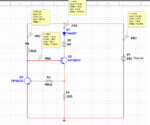
here is a simple bipolar current limiter.
current limiter.png

when the current thru resistor 201 rises, the voltage across the resistor increases above 1.2 volts and turns on the darlinton pair, which turns off Q2. You could replace the Q2 transistor with a fet if desired.

but if i were making a battery charger, i would use the same current sensing resistor, an op amp, and series pass fet to make a more "linear" current source. Long term i would want the 600 mA to drop to near zero (maybe 1 mA) as the battery becomes fully charged, so as to extend the battery life.
 
Smart charger for what type of battery?

Acid battery

- - - Updated - - -

here is a simple bipolar current limiter.
View attachment 139486

when the current thru resistor 201 rises, the voltage across the resistor increases above 1.2 volts and turns on the darlinton pair, which turns off Q2. You could replace the Q2 transistor with a fet if desired.

but if i were making a battery charger, i would use the same current sensing resistor, an op amp, and series pass fet to make a more "linear" current source. Long term i would want the 600 mA to drop to near zero (maybe 1 mA) as the battery becomes fully charged, so as to extend the battery life.

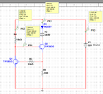
What's your opinion is about the circuit?

1.png
2.png

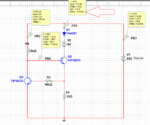
How would defuse the current fluctuations?

3.png
 

Hi,

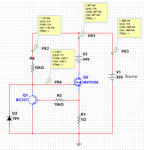
If you want 0.6A, then use about 0.9 Ohms fir R1.

I doubt the simulation is correct.
At a base current of less than 4mA it is about impossible to get 1.45A of collector current, due of limited hfe.
Especially if you want low dropout voltage.

What is the diode good for?

I recommend:
* Replace R1 with 0.9 Ohms
* replace Q1 with a standard signal NPN (now power NPN)
* replace Q2 with an N-Ch power mosfet. >=80V, >=2A, >=50W, needs heatsink
* add a 10V zener to limit V_GS
* replace R4 with 33k

Klaus

hi,
Thank you very much for your suggestion was excellent

1.png

Just a question if the battery charging current of 600 mA from 0 to 100 to be okay? After 1 hour to reach 55 volts, I'll stop charging

I do not understand the datasheet, how much charge current is best?
battery Datasheet
 

Hi,

With a power supply of 55.0V, I assume the current will be constant to about 54.4V battery voltage.
Then from 54.4V to 55.0V i assume the current will drop about linearely from 600mA down to 0mA.

Klaus
 
I do not understand the datasheet, how much charge current is best?
battery Datasheet
The data sheet says the maximum charge current should be 2.16A.

Generally the recommendation for good battery life is at the 10-hour rate for the battery capacity which would be 720mA for that 7.2AH battery.
 
Hello friends

How do I reduce power dissipation losses?
A lot of temperatures are generated
 

Hi,

There is no simple way to reduce power dissipation.
* reduce input voltage
* use switch mode technology

Klaus
 
I want using UC3842 to limit current

But I did not find the application circuit
 

Hi,

In the datsheet there is a current limitation description.
Maybe you could use/modify it.

***
But here is a common solution for many voltage regulators:
V_I_feedback.png
The shunt generates about 0.55V at 600mA....then the bjt becomes conductive and pulls the feedback pin high...this limits/disables the dutycycle

Stability of current limitation circuit depends on the regulator´s loop parameters and can´t be guaranteed by me.

Klaus
 
Status
Not open for further replies.

Similar threads

Part and Inventory Search

Welcome to EDABoard.com

Sponsor

Back
Top