Continue to Site

Welcome to EDAboard.com

Welcome to our site! EDAboard.com is an international Electronics Discussion Forum focused on EDA software, circuits, schematics, books, theory, papers, asic, pld, 8051, DSP, Network, RF, Analog Design, PCB, Service Manuals... and a whole lot more! To participate you need to register. Registration is free. Click here to register now.

TV transmitter connection with antena....

Status
Not open for further replies.
I have designed a VCO with avaricap for tuning from 175MHz-203MHz.It's quite low noise oscillator and stable in simulation.
If you would , I can post schematic here.It would be a practical experience for you.


Hey, it would be great, please post the schematic if you can! Can you explain also how would I use that?

I certainly did not give up.

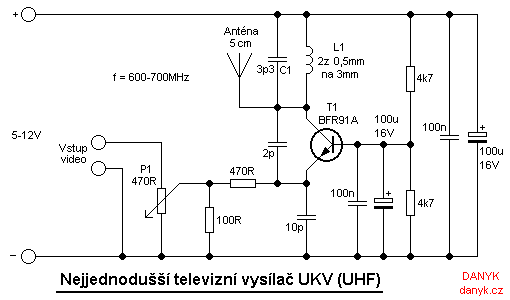
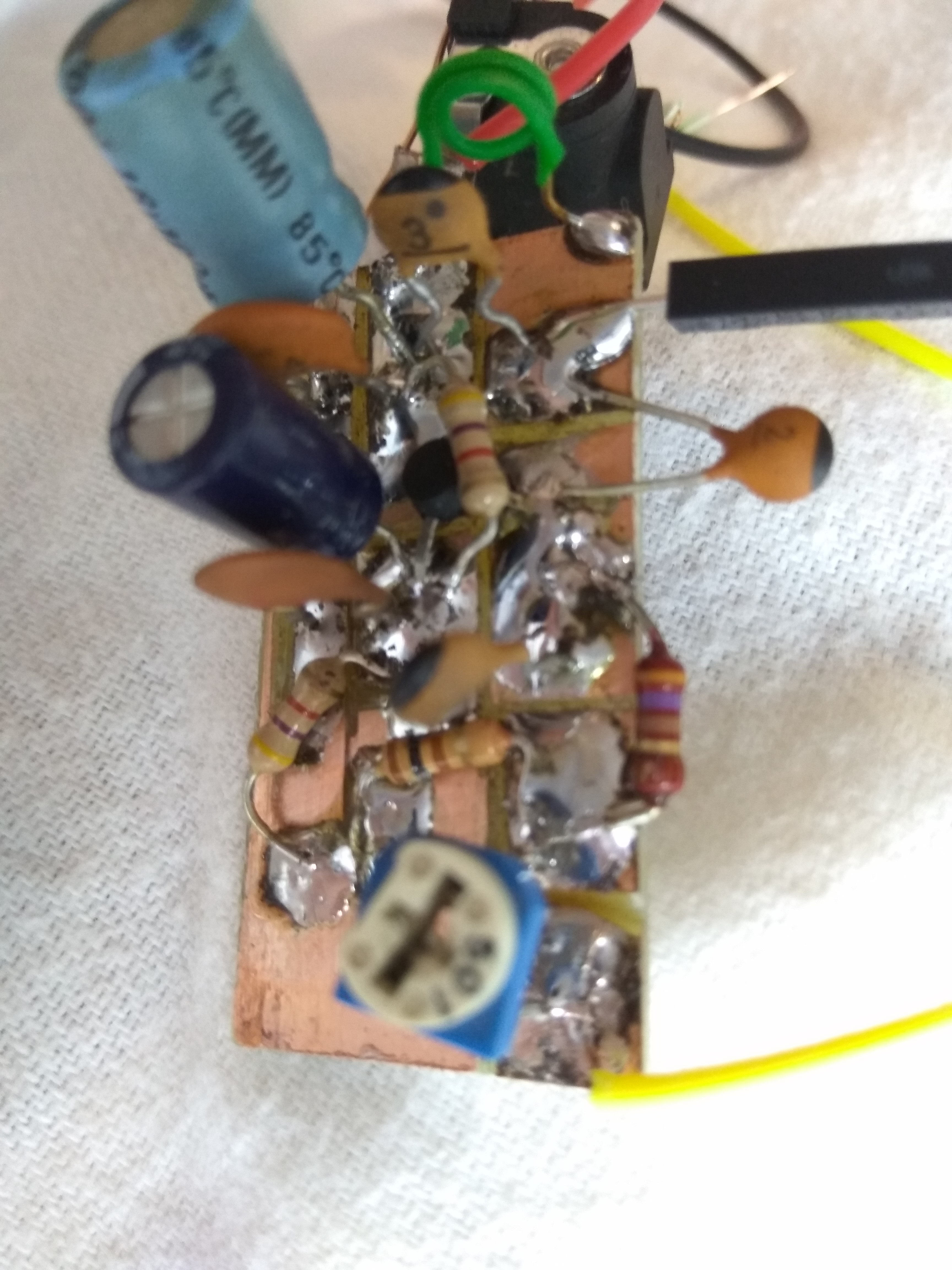
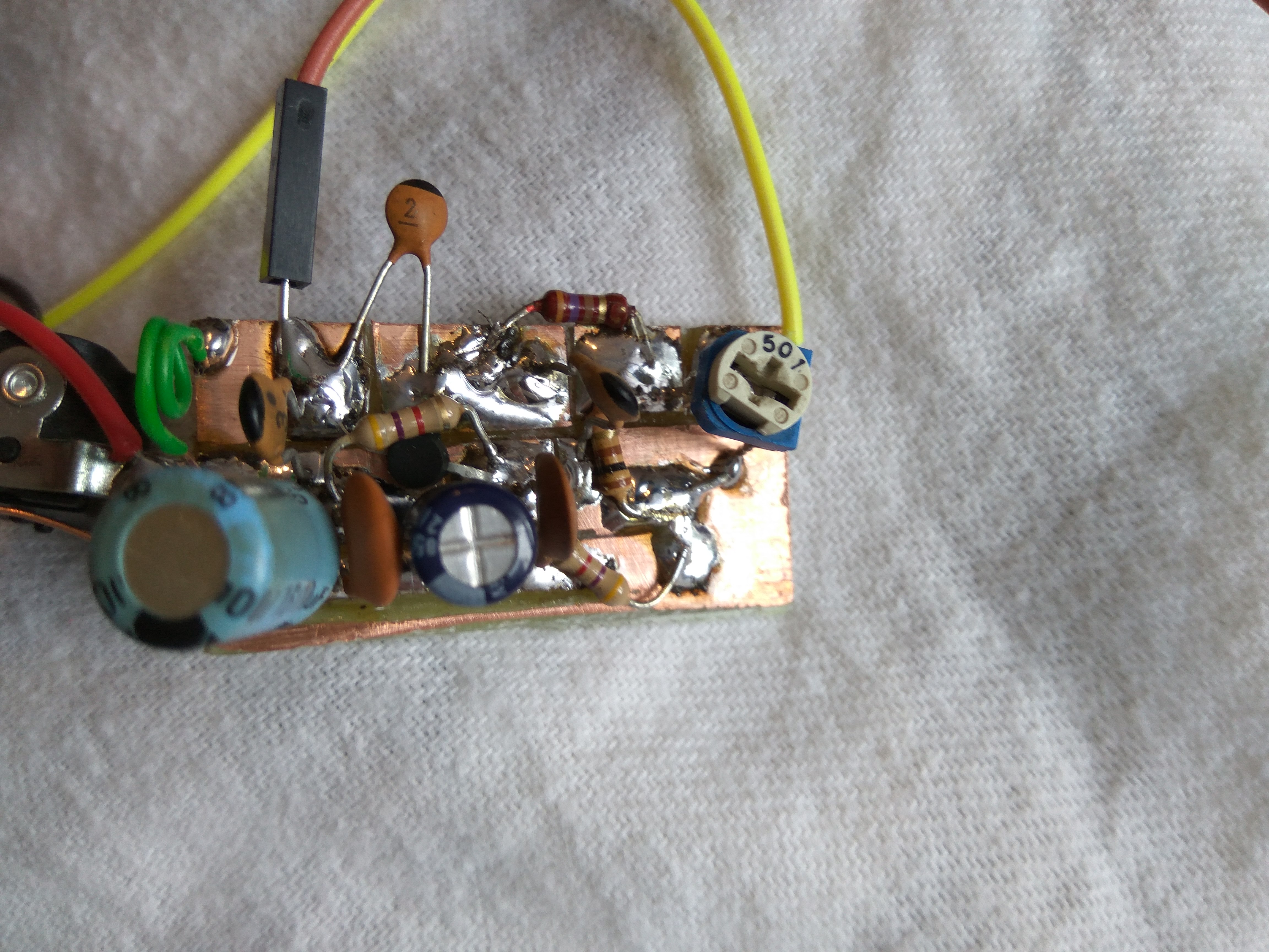
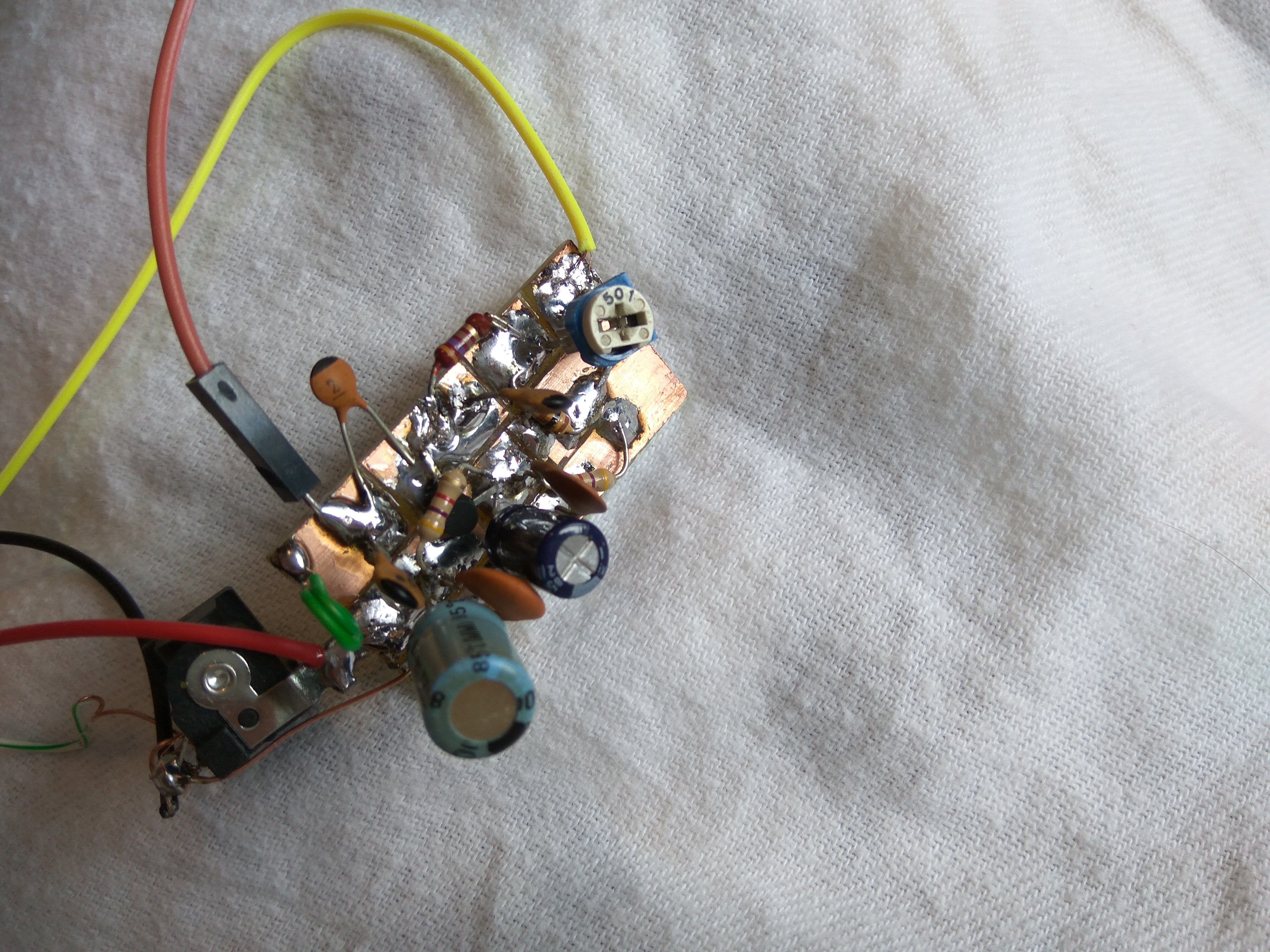
I have tried again with modified schematic (BC547):

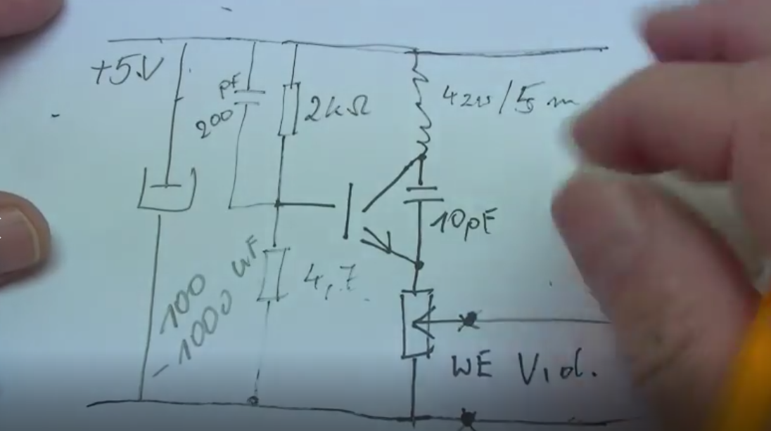
this is from this video:
https://www.youtube.com/watch?v=Qrbb5TgZUi8
this guy has removed few parts, including DIODE and capacitor from the schematic from first post and still had a good quality with 5V supply....

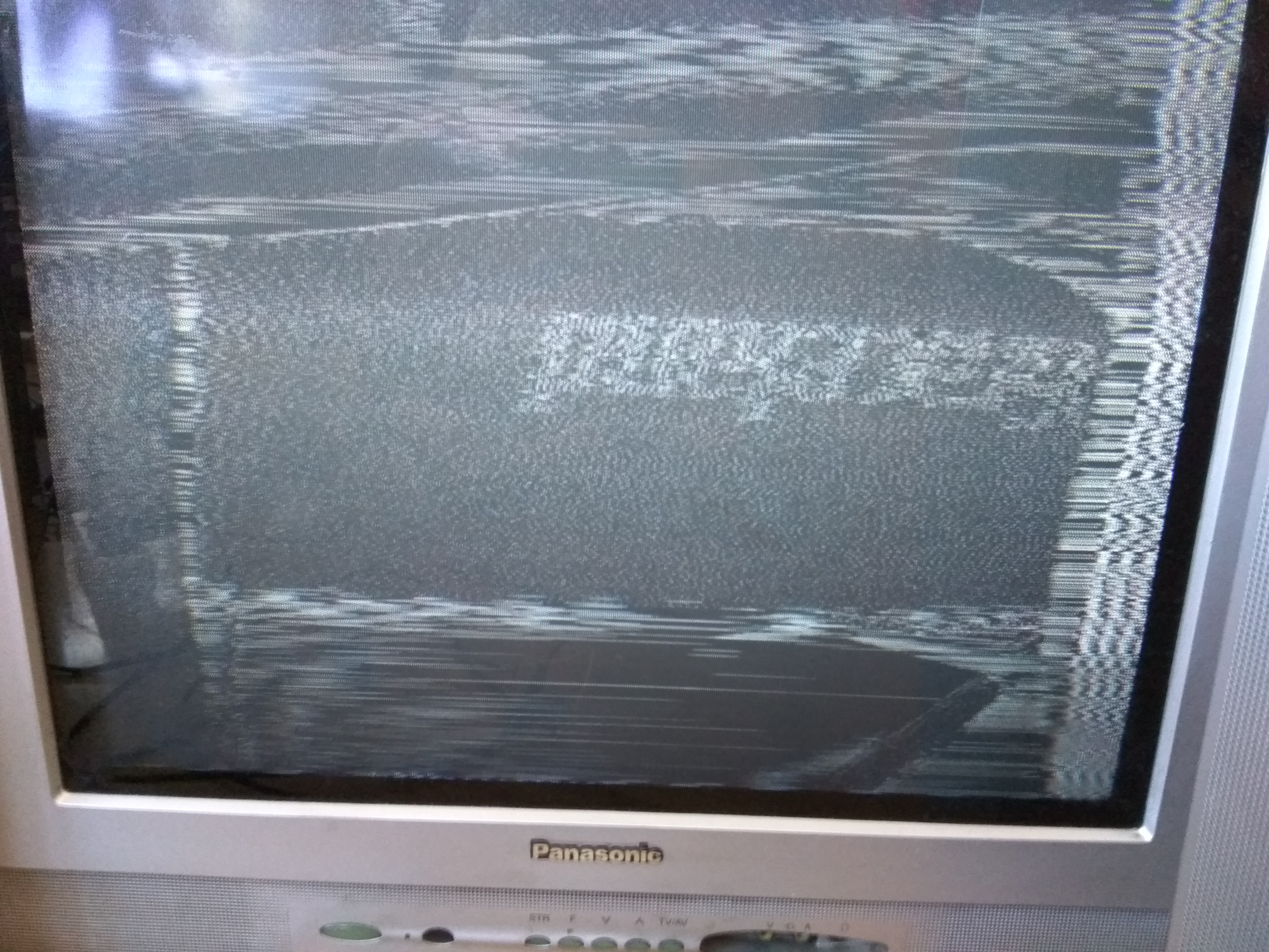
I tested it, it seems to give a slightly better results, but the screen is still tearing or very not readable.
 

Hey, it would be great, please post the schematic if you can! Can you explain also how would I use that?

OK,here is the schematic.It's working in simulation only, I have never tested on a board.
Vtune can be between 3V-10V.Use SMD components as possible.A carefully designed PCB with 2 layers with proper GND layer will help you much.
The VCO works between 175-203MHz with a pretty good Phase Noise.Output level is around 1.2-7.5dBm, Video Input can be as same as in your previous circuit schematic.
Don't apply too high video signal and not change 100 Ohm emitter variable resistor.( Use multi-turn high quality SMD variable resistor/trimpot )
GA3094AL: Coilcraft Air Cored Inductor(SMD)
BB689:Varicap Diode (SMD)
BFR193F:BJT (SMD)

200MHz_VCO.pngfreq. vs vtune.png
 
Last edited:

Thanks, what kind of software are you using to simulate this circuit?
Also, if you're designing it, can you design it for 500 MHz or so? It seems that most of the old TVs here are on such frequencies....

I'm afraid I will have toruble getting a varicap for that..
 

Thanks, what kind of software are you using to simulate this circuit?
Also, if you're designing it, can you design it for 500 MHz or so? It seems that most of the old TVs here are on such frequencies....

I'm afraid I will have toruble getting a varicap for that..

I'm using AWR Microwave Office.I can design also 500 MHz, no problem.
The varicap is BB689 of Infineon.( it's still available otherwise use an equivalent)
 

I have tried once with Danyk's approach:

http://danyk.cz/tvvys_en.html


This simple homemade television transmitter allows you to broadcast TV picture on the UHF band 470-855 MHz. The frequency is determined by the values ​​of components L1 and C1. The values ​​given in the schematic diagram set the transmitter to about 600-700 MHz, that is in the range of 37. - 50. channel of analogue TV bands. The television transmitter consists of a simple oscillator with high frequency NPN transistor. Suitable are for example BFR90, BFR91A, BFR92 or BFR93. I used BFR91A in the planar to50 case. Its transition frequency is 6GHz. Carrier frequency is amplitude-modulated by the input video signal. As the video source you can use a security TV camera or camera with video output. Antenna is about 5cm (2'') of wire and is connected directly to the oscillator. The transmitted signal can be tuned on any analog TV with UHF band. Operating frequency can affect by changing values ​​of L1 and C1. Fine tuning is possible by stretching or shrinking turns of L1. The television transmitter needs a supply of voltage about 5 - 12V. All live connections should be shortest due to parasitic capacity and inductance. Decoupling capacitors 100n should be as close as possible to the transistor. The electrolytes 100uF are in parallel to them, because it is necessary to effectively block frequencies from 50 Hz up to hundreds of MHz. Potentiometer P1 sets the modulation depth. Set it so that the image quality is good. Too deep modulation leads to too much contrast. At too low modulation level the image has low contrast and the vertical and horizontal synchronization may fail. The television transmitter can transmit any signal, for example PAL (50Hz) or NTSC (60Hz), important is what your television can display.
Tuning: Turn on the transmitter, connect the video source and search on an analog TV. Look for it around the 600-700 MHz or 37 - 50 channel. Some TVs with auto-tuning can skip the videosignal with no audio, so it is better to search manually.

I have used BFR91A ordered from Aliexpress.

The coil was made from two turns of Ethernet wire in isolation.

This is how I assembled this:


I have tested it with PAL camera signal source (worrks great without modulation when received by SCART).
I have tested it with two different TVs and two different 12V power supplies.
The best I got so far is:

Both TVs receive it on 65 channel (one of them is even a Czech TV, and the schematic author is Czech).

The modulation pot was in the edge level.
The video on the two TVs was simiiliar...


Anyone, really, any ideas? This is really the 4th circuit made by me for TV transmission so far and it's still not working. The same circuit worked great for Danyk.cz. What kind of mistake do I make?


Both TVs receive it on 65 channel (one of them is even a Czech TV, and the schematic author is Czech).
The modulation pot was in the edge level.
The video on the two TVs was simiiliar...


Anyone, really, any ideas? This is really the 4th circuit made by me for TV transmission so far and it's still not working. The same circuit worked great for Danyk.cz. What kind of mistake do I make?
Either there is a strong TV broadcasting channel on the frequency which you work on or your output signal is too high ( or its' harmonics ) so that the TV Tuner is saturated and TV looses H(V) synchronization.
The video signal might not be "clamped" or your oscillator works too bad..
Anyway, a RF circuit cannot be implemented as you have done.Try to search on working examples and correct them in according to "RF Principles"
 

The picture will never be perfect for the reasons already mentioned but it should be better than that.

What worries me is the light bar on the right edge, I wonder if it's the horizontal sync pulse which should be black, in fact below black level. If that is the problem, the video signal needs to be inverted (like a negative but the sync pulses are also upside down). The other rather remote possibilities are you are looking at the second harmonic and the unwanted FM produced by that circuit is distorting it or, as you have no sideband filter, you are looking at the wrong sideband and seeing a mirror image of the video.

Before going further, leave the transmitter alone and see if you can tune the TV to it on a lower channel number. The lowest numbered channel is the one it is actually transmitting on, anything higher is a harmonic.

Brian.
 

Status
Not open for further replies.

Similar threads

Part and Inventory Search

Welcome to EDABoard.com

Sponsor

Back
Top