Continue to Site

Welcome to EDAboard.com

Welcome to our site! EDAboard.com is an international Electronics Discussion Forum focused on EDA software, circuits, schematics, books, theory, papers, asic, pld, 8051, DSP, Network, RF, Analog Design, PCB, Service Manuals... and a whole lot more! To participate you need to register. Registration is free. Click here to register now.

Op-Amp Schmitt trigger saturation state

Status
Not open for further replies.

zionico90

Member level 2
Joined
Nov 28, 2013
Messages
48
Helped
0
Reputation
0
Reaction score
0
Trophy points
6
Activity points
369
Hi guys,

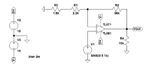
I have a common (I think) question related to the design of a schmitt trigger by using op-amp. In details I have to design a trigger with thresholds equal to +/- 1 V.
In order to do that, from the equation I have obtained that the ratio between the two resistance should by 14. Then I have realized the circuit by using R1= 4 Ohm (2.2+1.8) and R2 = 56 Ohm. For testing I have used a sinusoidal input (5Vpp and 1 kHz) and it seems that the circuit works with the proper thresholds. The problem is that when the state is "low" or "high", the op-amp saturate at V = 28.5 V! But the op-amp (TL081CP) is supply with a symmetrical +/- 15V.
Does anyone know where I'm wrong?


Thanks!
 

Hi,

My opinion:
* If you want a switching output, then use a comparator. It is designed for this.
* If you want a analog output, then use an Opamp. It is designed for this.

To your description:
I doubt a TL081 is able to drive a 60 Ohms load (4 + 56) with good output levels.
The whole circuit is not clear, therefore (like so often) show us your complete schematic...with part values, power supply and signal details.

Klaus
 

Yes, you are right! I was referring to 4k + 56k.
Here in annex the complete circuit that I have implemented.

Thanks!
 

Attachments

  • EX.png
    EX.png
    15.8 KB · Views: 83

Hi,

It is impossible for the output to go beyond supply rails.
How do you come to 28.5V? Where and how did you measure it?

Klaus
 

hmmmmmmmmmmmmmm. :thinker:
Most likely he is probing from V- supply to the output, instead of ground to output.
 

The TL081 has a problem when an input voltage gets within a few volts from the negative supply then the output goes as high as it can which will happen when it is used as a comparator.
 

The circuit shown in post #3 doesn't exceed TL081 common mode range and is expected to work well with the real part.

Are you reporting a real circuit or simulation problem?

There's no TL081 model shipped with Ltspice, please clarify which model you are using. Or better, post the zipped *.asc and used TL081 model file.

If a real circuit problem, your circuit is probably different from the schematic.
 

Status
Not open for further replies.

Similar threads

Part and Inventory Search

Welcome to EDABoard.com

Sponsor

Back
Top