- Joined
- Jul 4, 2009
- Messages
- 16,235
- Helped
- 5,140
- Reputation
- 10,309
- Reaction score
- 5,120
- Trophy points
- 1,393
- Location
- Aberdyfi, West Wales, UK
- Activity points
- 137,396
Almost all tunable receivers use the 'superhet' principle because it has so many advantages for little extra cost. As you have noticed, as you tune the oscillator you select a different input frequency but the antenna filter isn't tuned for best results on that frequency, it is set to give a broader 'band pass' characteristic which is a compromise between keeping unwanted signals out while not losing too much of the ones you want. To get best results all the tuned circuits would have to be set to the same frequency and that causes all kinds of problems with keeping them aligned. The solution used in Superhet designs is to move (VFO & mixer) the incoming signal to a fixed frequency (IF or Intermediate Frequency) so the filter stages do not have to be tuned each time. It isn't that much different to the direct conversion you have at the moment except that instead of converting directly to audio, you convert to a fixed higher frequency instead and later convert that back to audio.Isn't this method also used in TV tuners? I am planning to use one in the FM receiiver, afaik they output the "intermediate freq" which I have to somehow convert to audio...
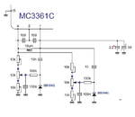
The limit of tuning range is decided by the varicap diode. It works like a variable capacitor where the voltage across it determines the capacitance. The voltage from the wiper of the pot changes as you rotate it and that in turn makes the capacitance across the diode change. To get a wider tuning range you have to make the difference between capacitance at low voltage and at high voltage as big as possible. You can set the widest tuning range by setting the two pre-set potentiometers to minimum resistance so you get the full 8V variation across the diode. The value of the pot makes no difference except that if you use a lower value it will heat up slightly and that makes the tuning drift worse. You used a BB329 varicap which has a range of about 10pF to 45pF but the original was a BB104 which has a range of about 25pF to 70pF so you will get a little less tuning range anyway.But let's back to the receiver of this topic. So indeed a second tuning knob would be useful...
What would be the best way to add it to schematic discussed here? Just add a second, for instance, 1k pot next to 10k pot?
Yes, two filters are needed, there is no way around that I'm afraid. The easiest way is probably to use a small DPCO signal relay as there are two connections to change. The ground side of the two filters can stay permanently connected but you do need to swap the antenna and MC3361 connections over.Also, I am planning to do a 40m/80m band version of this receiver.
I know that I must change antenna filters and VFO for other band.
As for antenna filter, I realize I will have two separate filters, right? And just... switch them somehow?
But what about VFO? I guess it would be simples with DDS...
You could use another relay to change the VFO frequency. There are electronic methods of doing the switching but I'm hesitant to suggest you do it as there are all kinds of technical complications and the PCB layout is critical, for certain there is no way it would work without a ground planed double sided PCB.
DDS is a possibility and it has several advantages, in particular you know exactly what frequency you are tuned to. It isn't quite as simple as just 'plugging in' a DDS device though as they do need to be electronically programmed to the frequency you want. DDS systems also tend to produce output frequencies different to the one you want at the same time. The strongest output will be the one you program it to produce but there will be some lower level signals as well which you may have to guard against as they may make the receiver pick up 'ghost' signals from some other frequency.
General rule at RF is to keep the wiring as short as possible, particularly at higher frequencies. You can move the audio stages off to a different board as the frequencies are low enough that wiring length isn't too important. Certainly keep the filters and the VFO as close to the MC3361 as possible, that's why I suggested using relays earlier instead of running wires to mechanical switches.I also wonder which parts of circuit I can put on separate boards without having too much stray inductances impact...
Brian.

