Continue to Site

Welcome to EDAboard.com

Welcome to our site! EDAboard.com is an international Electronics Discussion Forum focused on EDA software, circuits, schematics, books, theory, papers, asic, pld, 8051, DSP, Network, RF, Analog Design, PCB, Service Manuals... and a whole lot more! To participate you need to register. Registration is free. Click here to register now.

PTC overcurrent protection

Status
Not open for further replies.

hemnath

Advanced Member level 3
Joined
Jun 24, 2012
Messages
702
Helped
61
Reputation
120
Reaction score
57
Trophy points
1,308
Location
Chennai
Activity points
6,588
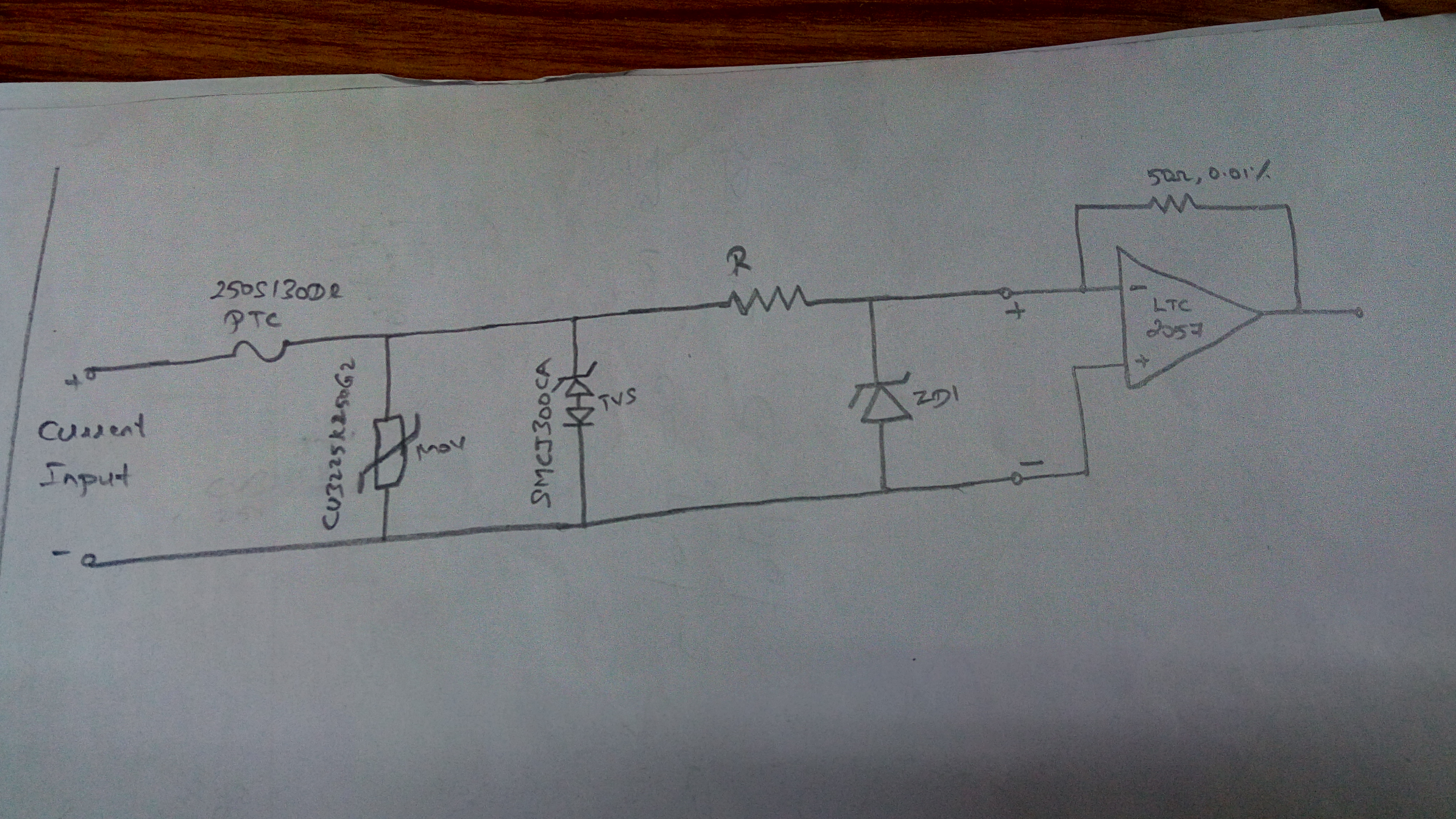
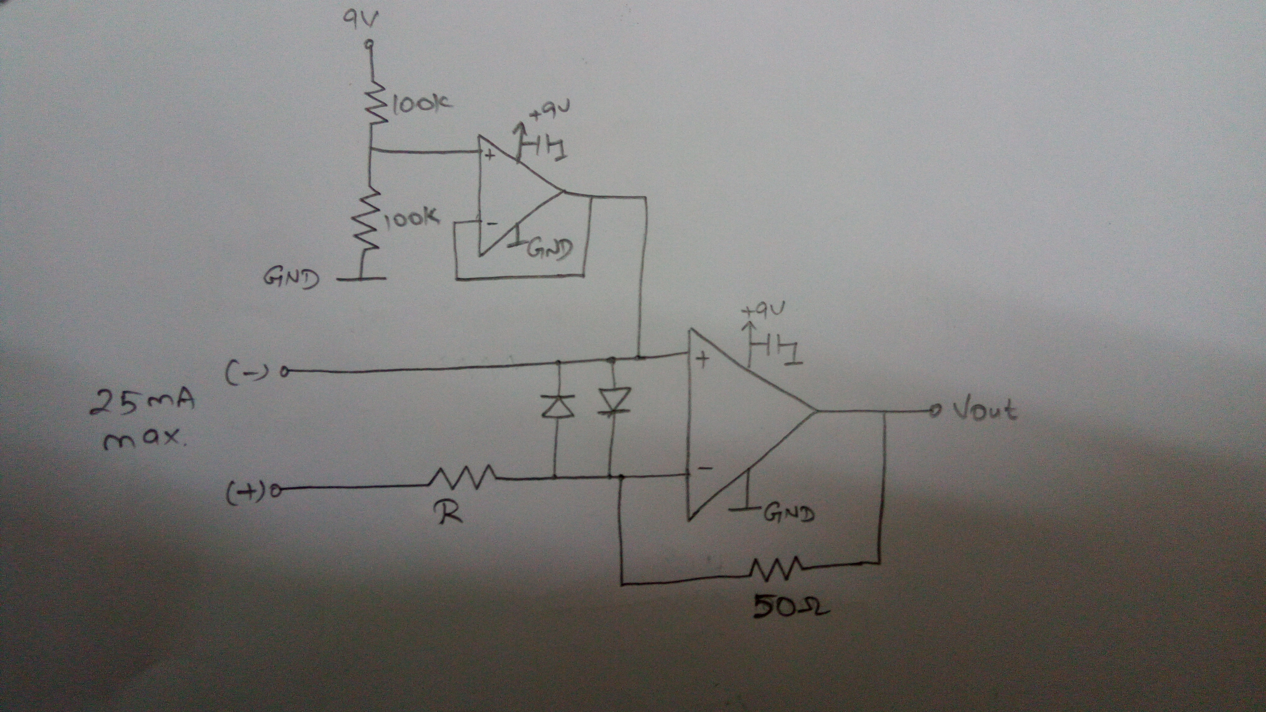
I am working on a transimpedance amplifier current to voltage convertion where the input current is 25mA(max). I want to add some protection on the input side. Should I use Littlefuse PTC resettable fuses? If accidentally, the terminals are applied to 230V AC, the fuse should protect the circuit.

I have selected the Littlefuse part no: 250S130DR. Is that right? Please share your knowledge. Thank you.
 

Doesn't work. PTC fuses are slow acting, simply assume Imax=Vmax/Rmin. Respectively you get several ten ampere with 230V at least for some 10 ms, "reliably" destroying small semiconductor devices and SMD resistors.

For 230V safety, you need a staggered protection, PTC, large TVS diode, series resistor, second clamp stage.


INPUT CURRENT MAX: 25mA. Is this circuit will protect the circuit when input terminals are accidentally applied at 230V AC?

How to calculate the resistor value and wattage?

Please help.
 

Is this circuit will protect the circuit when input terminals are accidentally applied at 230V AC?
Unlikely.

You should have
- a PTC fuse with 230V operational voltage and also much smaller trip current, e.g. 50 mA.
- a low voltage bidirectional TVS, e.g. a few V
- MOV is useless here

Useful resistor dimensioning depends. What's the acceptable voltage drop of the current sende circuit?
 

On a product catalog "CEP1000", it is mentioned that
Input protection Fuseless, up to 250 V AC

Which means, it can protect the circuit if the terminals are subjected to 250V AC?
 

Which means, it can protect the circuit if the terminals are subjected to 250V AC?
Should be read this way.

I know that it's possible to protect a 20 mA loop against accidental 230V AC connection. But not with the circuits you have posted so far.
 

Can I use this configuration for protection?


Your ideas please.
 

R and diodes must withstand the peak currents when applying 230 V AC. Is R a PTC?


The circuit has no protection against common mode voltage, can work if it's battery powered with insulation suitable for 230 V.
 

R is just a resistor with higher wattage. Can you please guide me in selection of resistor value calculation and selecting the diodes?
 

Hi,

I assume the complete circuit could be simplified.

Especially with the feedback resistor of 50 Ohms...
What is your input current range? (And your output voltage range?
What voltage drop is allowed?
Where does the voltage signal go to? ADC? What exact type?

Klaus
 

input current current: 25 mA max. Output voltage: 0 to 1.25V(25mA * 50E)
less than 200 uV input voltage drop.
Yes it goes to ADC, LTC2410
 

Hi,

If I calculated correct, then your total measurement resistance must be less than 8mOhms.
A piece of wire...but I doubt you will find any protection circuit that is able to achieve this.

Or the specification is not correct...Why only 200uV?

Klaus
 

Sir,

Designing a circuit like zero resistance ammeter. The more common name for it is transimpedance amplifier.

The big advantage of TIA is that is has zero voltage drop on its terminals so it does not affect the circuit being measured – unlike a regular multimeter.
 

Hi,

If you want zero drop, then I see no chance for a series connected PTC...it surely will cause voltage drop..and the voltage drop will depend on temperature...

Let's say 10mV is allowed...this usually should be no problem (what's the application, that just allows 200uV?)
Then you need a resistor (shunt) with R = V / I = 10mV / 25mA = 0.4 Ohms.
Use a voltage amplifier: gain = 1.25V / 10mV = 125 to get the desired ouput voltage of 1.25V @ 25mA.

If you use a 1W rated shunt, then it will withstand overcurrents up to 1.5A DC without additional protection. Not bad for a 25mA rated device.

Klaus
 

It's simply not possible to design a 250V protected current input without some voltage drop in the current path. If 0V input voltage is actually an objective (I doubt it is) then you can design a circuit with separately protected source and sense lines.
 

That's an I/V converter without any protection.

As mentioned in my previous post, you need to protect source and sense separately if you want to keep the I/V converter low input impedance, but none of your circuit ideas (post #3, post #7) does.
 

Status
Not open for further replies.

Similar threads

Part and Inventory Search

Welcome to EDABoard.com

Sponsor

Back
Top