Continue to Site

Welcome to EDAboard.com

Welcome to our site! EDAboard.com is an international Electronics Discussion Forum focused on EDA software, circuits, schematics, books, theory, papers, asic, pld, 8051, DSP, Network, RF, Analog Design, PCB, Service Manuals... and a whole lot more! To participate you need to register. Registration is free. Click here to register now.

Op amp output voltage

Status
Not open for further replies.

afr123

Junior Member level 1
Joined
May 23, 2017
Messages
18
Helped
0
Reputation
0
Reaction score
0
Trophy points
1
Activity points
211
Hi,

I have a basic question.

Suppose my op-amp supply voltages are +/-12V and the input signal is 10V ac signal. Now if the gain (set by feedback and input resistor) is lets say 5. What would be my output? I think the opamp should clip the voltage above the max. supply and below the min. supply. If this is the case, will it damage the op-amp?

Thanks
 

Standard op amps typically go to within about a volt or so of the rails.
Rail-rail type op amps will go to very near the rail voltages, depending upon the output load.
 

Hi,

will it damage the op-amp?
Someone said: no

I say: it depends.
It depends on the circuit, on the Opamp and on the input signal.
What does 10V AC mean? What waveform? What amplitude?

Let's say sine with 10V RMS. This means +/-14.1Vp.
This is more than the supply voltage! And some Opamps don't like this ... and maybe their internal protection diodes get damaged.

Klaus
 
  • Like
Reactions: CataM

    CataM

    Points: 2
    Helpful Answer Positive Rating
The input signal is higher than the supply voltage which might destroy the opamp. Why not use an voltage divider attenuator at the input? If the opamp survives then since the gain is 5 then of course the output of the opamp will have severe clipping. The output cannot go higher than the supply voltages, sometimes a few volts less when loaded.
 

My point was that input voltage is less than supply voltages. Suppose +/-10Vp but the gain is 5. Then ideally speaking I should get +/-50Vp at the output but because the supply is just +/-12V so it will clamp the voltage to +/-12V without damaging the op-amp. Am I right?

Secondly, I want to read the output of the piezoelectric transducer. So some op-amp stages are needed to amplify the signal before giving it to ADC. But there is one problem, when the piezoelectric transducer is subjected to shock/force etc, it can generate voltages in kV range but for a few microseconds. So, I want to design some circuit to protect my op-amps. I read about the TVS diodes but am not sure how to use it. Any ideas?
 

With a +/-12V supply, most opamps outputs will not exceed about +/- 11V or a little less. Clipping does not harm an opamp, its many harmonics might damage a tweeter.
 

Okay. Thank you.

I have another question. For my design, I plan to connect the output of my opamp to an audio amplifier. And the output of the audio amplifier to the transformer (1:10) to drive the ultrasonic transducer. I have measured the impedance of the transducer and it is around 1000 ohms (R+jX). I want to match this impedance. So what I am thinking is to use resistance and capacitance at the primary side to match the load.

As the input is +/-10V, the output at the secondary will be +/-50V after matching (assuming perfect matching). From circuit point of view, is it a good design or can it be made better?
 

So what I am thinking is to use resistance and capacitance at the primary side to match the load.
´
It's rarely reasonable to use resistors for power amplifier impedance matching, except you want to trade efficiency against bandwidth.
 

The only reason to match a load resistance is to eliminate reflections in a transmission line.
You are confusing matching the load resistance with matching the source resistance.
Matching the source to the load will waste half the power.

You match the load to the source resistance (not vice versa) for maximum power transfer but an audio amp has such a low output impedance that you never do that for such amps.
Doing that will overload the amp output with excessive current and it will fail.
 

It would be probably helpful to know the application problem, type of ultrasonic transducer, intended transmitted signal.

I have measured the impedance of the transducer and it is around 1000 ohms (R+jX).
1000 ohms is a real impedance, so the statement makes literally no sense. Or do you want to say that you see 1000 ohms real impedance in transducer resonance? If so, is it impedance minimum or maximum of the resonance curve?
 

I swept the frequency from 35kHz to 45kHz and using vector network analyzer, I checked the impedance. The ultrasonic transducer is made for around 40kHz freq. Obviously, the impedance was not constant as ultrasonic transducers has capacitive behavior. And yeah, it is not real impedance but complex. I won't be using it for a single frequency.
 

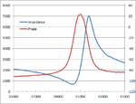
That's my measurement of a 40 kHz transducer (Multicomp MCUSD14A40S09RS-30C)

MCUSD14A40S09RS-30C.png

The impedance is only capacitive far away from the resonance. You get the characteristic combination of a low impedance series resonance and a high impedance parallel resonance. Respectively there's no reasonable way for a wide band impedance matching. Usual termination for maximum bandwidth in send/receive application, e.g. echo sounder is with a resistor corresponding to the series resonance impedance, about 700 ohm for the shown transducer.
 

Status
Not open for further replies.

Similar threads

Part and Inventory Search

Welcome to EDABoard.com

Sponsor

Back
Top