Continue to Site

Welcome to EDAboard.com

Welcome to our site! EDAboard.com is an international Electronics Discussion Forum focused on EDA software, circuits, schematics, books, theory, papers, asic, pld, 8051, DSP, Network, RF, Analog Design, PCB, Service Manuals... and a whole lot more! To participate you need to register. Registration is free. Click here to register now.

Is this configuration of MCP23S17 right?

Status
Not open for further replies.

tony_lth

Advanced Member level 5
Joined
Jul 28, 2010
Messages
2,086
Helped
377
Reputation
756
Reaction score
368
Trophy points
1,363
Location
Beijing
Activity points
12,623
Hi,
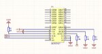
I want to use several GPIOs to control 10+ LED, so I selected MCP23S17 IC.
I wan to use 2 GPIO to simulate SPI interface to control MCP23S17 IC.
I am not sure about my config, pls comment, thanks.
1. _CS link to GND is right? In code, if it is needed to set _CS to 1 or 0?
2. The STM32 only set MCP23S17, and doen't need feedback from MCP23S17, so SO in NC, OK?
3. Do SCK and SI need 10K pullup to +5V or +3.3V?
4. I saw some design leave INTA and INTB NC, do these int need config by SW ? Or my design just link them to GND, right?
 

Attachments

  • 捕获.JPG
    捕获.JPG
    105.8 KB · Views: 78
  • MCP23S17-E_SS 21952b-70868.pdf
    640.9 KB · Views: 68

Hi,

First I was confused, because you talk about GP pins used as SPI...and you talk only about the MCPxxx, which has GP pins.
But later I realised you meant GP of an unknown microcontroller.

Btw: there are lots of solutions that use HC595. Simple, good available and cheap.

1) CS = LOW?
--> why don't you read the datasheet? It clearely says:
* The SPI xxx operation is started by lowering CS.
* The sequence ends by the raising of CS.


2) so SO in NC, OK?
Outputs my be left open, when not used.
But the SI of the microcontroller
--> general rule: Don't let any unused input floating. Either pull it to valid HIGH, or valid LOW

3) Do SCK and SI need 10K pullup to +5V or +3.3V?
--> both should be push pull (totem pole) outputs. No need for pulling them with resistors..

4) INTA, INTB
--> Why don't you read the datasheet? It clearely says:
* Interrupt output for PORTx. Can be configured as active-high, active-low or open-drain.

Klaus
 
Hi, Klaus,
Thanks.
I am sorry not to make the GPIOs clear, which are from a STM32 output.
About INTA/B, although the datasheet said they can be high/low/open, I want to clarify in my circuit their status.
Soon I will paste the circuit using HC595, which should be a good idea.
Best,
Tony Liu
 

Hi, ALL
Attachment is the HC595 circuit for I/O expander.
Welcome to comment.
 

Attachments

  • 捕获.JPG
    捕获.JPG
    99 KB · Views: 96

Status
Not open for further replies.

Similar threads

Part and Inventory Search

Welcome to EDABoard.com

Sponsor

Back
Top