Continue to Site

Welcome to EDAboard.com

Welcome to our site! EDAboard.com is an international Electronics Discussion Forum focused on EDA software, circuits, schematics, books, theory, papers, asic, pld, 8051, DSP, Network, RF, Analog Design, PCB, Service Manuals... and a whole lot more! To participate you need to register. Registration is free. Click here to register now.

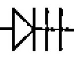
Have you ever seen a 3-Cathode diode in an schematic circuit?

Status
Not open for further replies.

antonio.diaz

Newbie level 4
Joined
Jun 5, 2017
Messages
6
Helped
0
Reputation
0
Reaction score
0
Trophy points
1
Location
Monterrey, Mexico.
Activity points
64
Hello everyone,

I would like to know if any of you has seen the representation of a diode with 3 cathodes.

I know that the representation of a diode with two cathodes (or two plates at the cathode) is a varactor, but I did not find any information about a diode with three plates at the cathode.
Here is an image of the component that I am trying to find:
3k-diode.JPG

So, do you know what kind of diode/component is this? ---|>|||---

Any help is appreciated.
Thank you.
Regards,
ITM Antonio Diaz.
 

I know of no such component. Either it's a printing error or someone did a 'cut and paste' without lining it up properly.

It could be a varactor or a diode with a capacitor in series or just an error, can you post the surrounding circuit so we can see it in context please.

Brian.
 

or a diode with a capacitor in series

I would bet on this guess; the standard symbol of a varistor does not have a line through the cathode plates. It actually looks like two superimposed symbols: A varactor in series with a capacitor, though a connection would be expected to come out between both.
 

Hello Brian,

Yes, here is the surrounding circuit where these components are included:
3k-diode-circuit.JPG
(XTC is a ground reference signal, the supply of the opamp is +/-15V)

I also was considering the idea of a printing issue, but I am not sure about it. The circuit looks quite simple, but I do not really know how it could affect if I use another kind of diode for this circuit and its final application.

Thank you.

Antonio Diaz.
 

That's a funky schematic and I'd think maybe these are
some sort of clamp diode (or diode string?). Might see if
you can find the associated BOM and see what oddball
diodes are found? You might also look for any kind of
local transfer function data / curves and see if a clamp
voltage short of the rails is produced, which would lead
to some idea about "diode" attributes. Maybe substituting
a back-back zener diode pair would do the job (but this
is prone to make noise and a stack of forward diodes,
antiparallel, might be used for this reason even though
sloppier tolerances etc.). Or because they wanted only
2V (3x0.7) and there is no 2V zener.
 
They're not varactor diodes because C101 swamps this at 10,000pF.
U30 says "OA412" but I can only find LF412?

I would guess this means could be one or two diodes in series, for each. Could be a messed up Schottky symbol

There are silicon varistors, but usually a diode symbol for them.

Easier to find out what this stage's output is clipped to by these mystery diodes.
 
My opinion is, that the schematic drafter just go lazy and figured out a way to indicate three diodes in series.

Anyways, this is a bounding circuit.
 
Hello schmitt trigger,

Yes, that could be a possibility, but in the BOM does not appear more diodes, so D56 and D57 are singles components.

But now, according with this idea, do you know if there are multiple diodes encapsulated in a single component? Maybe it would be easier to use zener diodes, but as dick_freebird said, it is not easy to find 2V zener diodes in the market.

I don't know jaja, we will not be sure until we simulate/test this circuit to figure out what is happening there.

Thank you.
Regards,
ITM Antonio Diaz.

- - - Updated - - -

Hello dick_freebird,

The problem is that the BOM I have does not show what kind of component is each of that list. I just have the component drawings and their names (D56, D57, R133, etc.).
Following is a complete stage of the circuit that maybe could help us to understand more about the probable nature of that mystery diodes:
3k-diode-circuit2.JPG

They seem to be clipping diodes, but the representation of them makes me doubt a little bit jaja :(. Anyway, viewing the entire circuit, I think that maybe it could be just a weird representation of a normal diode.

Thank you.

ITM Antonio Diaz.

- - - Updated - - -

Hello prairiedog,

Yes, it is an LF412.
Please refer to the answer I give to dick_freebird, there is another image of the entire circuit. As I said, I don't se anything special about this circuit, so I agree with you with the idea of a messed up representation of a well known type of diode.

Thank you.

ITM Antonio Diaz.
 

I believe there are (or have been previously) 2- and 3-fold series connected Si-diodes available, used as low voltage zener diode supplement. The asumptions by dick_freebird sound plausible.

The shown symbol is non-standard and not actually helpful.
 
It's a big glorious window-comparator for zero-cross detection?
U30 feeds (differentiator) clamped zero-cross pulses in.

D55, D54 make a +/-Vf reference, so D56,D57 need to have a greater output. That is the problem I think.
Said another way, D56, D57 need to have greater forward-voltages than D55, D54.
If they don't, no output from the differentiator portion of the window-comparator. I might be wrong.

For multi-diode parts, I use BAV99 SMT parts.
 

Status
Not open for further replies.

Similar threads

Part and Inventory Search

Welcome to EDABoard.com

Sponsor

Back
Top