zubair.mehmood
Newbie level 4
hi
i have made a balun with single ended input and differential output. My questions are:
a) when and why we should AC ground the center tapped terminal?
b) i have made the matching at input which was single ended but how will i made it for the differential output. i figured out the values of the component for differential side as shown in figure (attachment), but how i will select these values for two differential lines?
thanks
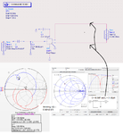