Continue to Site

Welcome to EDAboard.com

Welcome to our site! EDAboard.com is an international Electronics Discussion Forum focused on EDA software, circuits, schematics, books, theory, papers, asic, pld, 8051, DSP, Network, RF, Analog Design, PCB, Service Manuals... and a whole lot more! To participate you need to register. Registration is free. Click here to register now.

full details on creating good sound

Status
Not open for further replies.
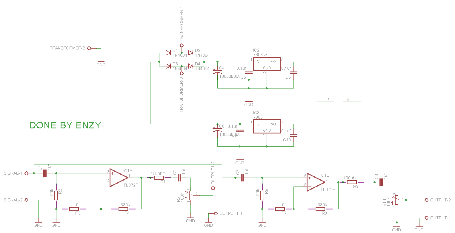
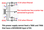
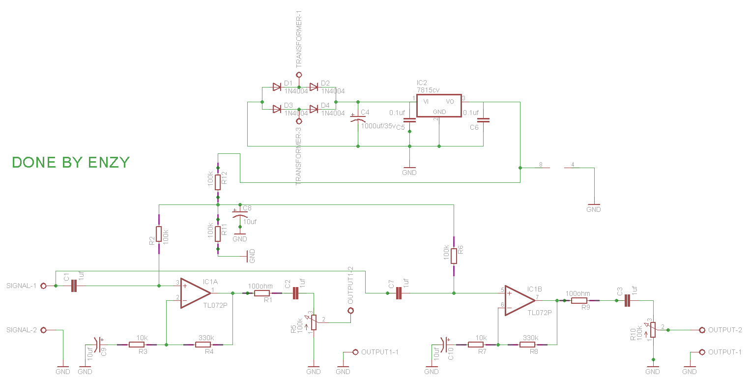
Now your transformer produces 24VAC so its peak voltage is too high at 34V. Didn't you read the datasheet for the Texas Instruments uA7815? It says its maximum recommended input is 30V.
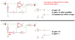
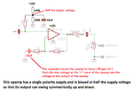
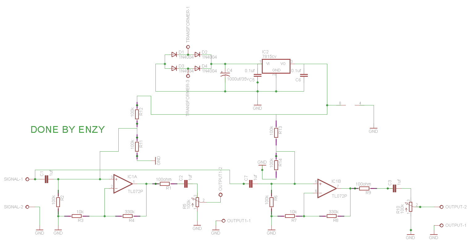
Your supply has a single polarity and the opamps are biased at ground so when the input swings negative then the opamps rectify the sound producing severe distortion and might be destroyed.

Why don't you understand that the opamps with a single polarity supply MUST be biased at half the supply voltage so that their output can swing up and down with the audio signal??
An opamp with a dual polarity supply is biased at 0V (which is half the supply voltage) so that the output can swing up and down.

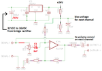
Again, your opamps amplify DC, look here:
 

Attachments

  • opamp.png
    opamp.png
    19.6 KB · Views: 105

Ok im using a L7815cv isnt that 35-40vdc input rated. I thought you said you didnt use dual polarity supplies at all.

As for the biased talk I actually didnt understand, If I use a dual polarity supply that means the supply is biased at 0V. if I dont use a dual polarity supply how else would I bias the supply voltage halfway?

you also asked why dont I understand, but my question would be how could I understand something that I dont know, let me say it once more im very young and im just a hobbyist, before now all i did was to follow a schematic i see online and make it now im trying to learn, so at the stage I am I dont think I can understand something before Im not aware of.

- - - Updated - - -

Well hopefully I understand what you said.


Im wondering if a 12v transformer can now work.
 

I am new here, but I designed hifi power amp as hobby and I just finished a power amp with THD at 0.0015% below 10KHz and 0.0035% at 20KHz into 4ohm at 112W output power. I just have it in my system for a week and it's definitely better than the Nakamichi PA-7 Stasis amp designed by Nelson Pass of Threshold and Pass Lab.

If you want to design it yourself, you need to study. I spent a lot of time studying, there is a lot of detail and very specialized knowledge that even though you might be a long time design engineer, you need to button down and study. The book I suggest is https://www.amazon.com/Designing-Audio-Power-Amplifiers-Cordell/dp/007164024X/ref=sr_1_1?s=books&ie=UTF8&qid=1496817395&sr=1-1&keywords=bob+cordell

I studied this book pretty much from cover to cover before I design my amp. Bob was an analog IC designer like me before, power amp is just a huge discrete opamp. There are a lot of knowledge that is transferable from IC opamp design to power amp design. I verified quite a bit of his formulas, using the IC design book by Grey and Meyer, I yet to find any error. It's a very good book.

If you want to find good circuit and just either buy pcb or DIY, you should go to www.diyaudio.com and talk to people there. They are experts, even Nelson Pass are there answering questions. You can look at his stuffs, those are really really high end stuffs. If you are into hifi, you should know him and his famous Threshold Stasis, Aleph and his passlab amps that worth over $10K!!!! Just go there.

As for me, I design my own, not copying anyone, from scratch. Layout my own pcb, drill every single hole and put everything together. Even though it is similar to some standard design, I push the limit all the way to get this low distortion. It definitely have more detail, better sound stage and better separation than the Nakamichi Stasis that is almost the same circuit as Pass's Threshold S300 power amp.
 

As for the biased talk I actually didnt understand, If I use a dual polarity supply that means the supply is biased at 0V. if I dont use a dual polarity supply how else would I bias the supply voltage halfway?
You do not bias the power supply, instead you bias the input of the opamp so that its output can swing equally up and down. I show how to bias the single polarity supplied opamp at half the supply voltage.

Im wondering if a 12v transformer can now work.
Nope. Your circuit is missing a very important center-tap on the transformer to give the supply a 0V ground reference. Also the transformer has a voltage that is too low.
 

Attachments

  • opamp biasing.png
    opamp biasing.png
    18.6 KB · Views: 96
  • dual polarity supply.png
    dual polarity supply.png
    11.4 KB · Views: 89

Nope. Your circuit is missing a very important center-tap on the transformer to give the supply a 0V ground reference. Also the transformer has a voltage that is too low.

The schematic I sent actually has the transformer connected to gnd just as how you have it I just can show a pictorial view like the one you sent because I dnt have that kinda diagram in the software I am using.

I now understand what you mean by biasing the input of the opamp. So once im making a preamp circuit its required to bias the input with half the supply voltage? is it the most efficient way of biasing the input or its not critical to use another method

- - - Updated - - -

Ill have a transformer issues I can only get 12v transformers not unless ill just have to pull up one of them and add a few turns to get probably about 14vac

- - - Updated - - -

the voltage divider that is used to bias the input of the opamp I was wondering If I should only use one to supply both opamps or is it ok the way I did it.


You said your transformer has a center tap but is it 24V or is it 6V + 6V? If it is 6V + 6V then the regulator can be a 7810 (10V).
Your new circuit has R2 in the wrong place causing the input bias to be 5V instead of 7.5V.
A very important capacitor is missing in the feedback so its DC gain is 34 and the opamp is trying to force its output to 5v x 34= 170V or as high as it can without an output signal.
Another capacitor is missing that filters the voltage divider so if the the preamp has the other capacitor then it will amplify hiss from the regulator 34 times.

The TL072 opamps have Jfet inputs that have almost no DC input current so both opamps can be biased from the same voltage divider. The missing capacitor at the voltage divider keeps the two stereo channel signals separated from each other.
 

Attachments

  • errors by Enzy.png
    errors by Enzy.png
    31.7 KB · Views: 83

The schematic I sent actually has the transformer connected to gnd just as how you have it I just can show a pictorial view like the one you sent because I dnt have that kinda diagram in the software I am using.

I now understand what you mean by biasing the input of the opamp. So once im making a preamp circuit its required to bias the input with half the supply voltage? is it the most efficient way of biasing the input or its not critical to use another method

- - - Updated - - -

Ill have a transformer issues I can only get 12v transformers not unless ill just have to pull up one of them and add a few turns to get probably about 14vac

- - - Updated - - -

the voltage divider that is used to bias the input of the opamp I was wondering If I should only use one to supply both opamps or is it ok the way I did it.


Looking at your schematic, you have a problem. You use single supply and bias the input above ground. But you have a DC feedback loop, your output will rail to the +ve 15V rail. You need to have a capacitor to AC ground the R3 and R7. That's when you might run into potential issue. You need to use high enough value of electrolytic so it really looks like a dead short as AC ground, you don't want to have any voltage develop across the capacitor or else you will create distortion as electrolytic cap has dC/dV issue and create distortion.

Also, TL072 is way too old for hifi. Change to the new generation opamps like OPA2604, OPA2134 or LM4562 type of ultra low distortion opamps.
 
  • Like
Reactions: Enzy

    Enzy

    Points: 2
    Helpful Answer Positive Rating
So that it does not clip when the volume control at the input of the power amp is at halfway then the opamp should have a supply more than 14V, because you said that, this is the reason I was using 15v to supply the circuit.


Enzy, your new circuit is correct!
I forgot that the first opamp will have clipping when the input level is high and the supply to the opamp is 14V or less.
You said you cannot find a transformer higher than 12V. Is the center-tapped transformer 6V + 6V or 12V + 12V? If it is 12V + 12V then it can feed a 7824 (24V) regulator.
I agree that the newer opamps listed are better on paper but they sound the same.
 

Looking at your schematic, you have a problem. You use single supply and bias the input above ground. But you have a DC feedback loop, your output will rail to the +ve 15V rail. You need to have a capacitor to AC ground the R3 and R7. That's when you might run into potential issue. You need to use high enough value of electrolytic so it really looks like a dead short as AC ground, you don't want to have any voltage develop across the capacitor or else you will create distortion as electrolytic cap has dC/dV issue and create distortion.

Also, TL072 is way too old for hifi. Change to the new generation opamps like OPA2604, OPA2134 or LM4562 type of ultra low distortion opamps.

Thanks for the correction, audioguru made the correction a while back but I forgot to include it and I'll try those opamps in the future when I buy some.

- - - Updated - - -

Enzy,
You said you cannot find a transformer higher than 12V. Is the center-tapped transformer 6V + 6V or 12V + 12V? If it is 12V + 12V then it can feed a 7824 (24V) regulator.

Isnt the maximum supply voltage to tl072 18V or is it 18+/- which would be 36v

sorry the transformers I have are 12-0-12v
 

The circuit should theoretically work. Things that I want to comment:

1) You put the volume pot at the output, this means the output impedance can go as high as 50Kohm(half way). Coax has about 30pF/ft, that can form a pole and roll off high frequencies. I designed my preamp with the volume pot at the input so I attenuate the signal before going into the amp. If you use one of the amp I suggested, amp noise is not going to be a problem. Also, if you put the volume pot at the output, this means you opamp is amplifying maximum amplitude. THD rises with output swing, you don't want to always at maximum volume. This is very important.

2) Your feedback resistor is 330K and 10K, it's too high for me. You might risk forming extra pole at the -ve input and might cause instability due to the extra pole. I would use 33K and 1K, then I would increase the AC grounding cap from 10uF to 220uF. Use a 0.1uF or 1uF ceramic cap in parallel. For my amp, I use AC grounding also, I use 2 of 100uF parallel with a 10uF and parallel with a 0.1uF to ensure it really stay as dead short at all frequencies.

since im new to this I would love Audioguru to comment on this

- - - Updated - - -

to me what you said about the volume control at the input make sense
 

A complete audio amplifier has a preamp and a power amp close together. Its volume control is at the middle, at the input of the audio amp so that noise produced by the preamp is reduced by the volume control being turned down most of the time.
I agree that if the power amp is far from the preamp then a pole is formed by the capacitance of the connecting shielded cable which causes high audio frequencies to be reduced. Then the volume control should not be at the output of the preamp, it should be at the input of the power amp. I can't remember if the Chinese power amp has it but don't most power amps have a volume control at their input?

I have made many audio circuits with TL07x audio opamps and used fairly high value feedback resistors with no stability problems. But all my circuits were properly laid out on a compact pcb. The high capacitance between the rows of contacts and the wires all over the place on a solderless breadboard might cause instability with high value feedback resistors. Usually I use film capacitors in series with the feedback resistor to ground because they do not produce the distortion and polarity problems of an electrolytic capacitor. My high value feedback resistors do not need a high value electrolytic capacitor but low value feedback resistors do.
 

ok I was giving Alan8947 time to reply but I guess he isnt online.

Audioguru can you double check this for me im about to create a board for this I even changed the symbols of the input and output capacitors to electrolytic caps i assume the polarites are correct.

the 100ohm resistor at the output of the opamp is to reduce noise is it necessary for a crispy clean sound.

- - - Updated - - -


To OP, you said you want to wait for second opinion, that's the reason I did not say anything more.

You want good sound in your original post, I take it for highest quality audiophile. For normal stereo hifi, it's a lot more forgiving, TL072 is perfectly fine. But I am talking about audiophile if you want good sound.

I tried with output driven by volume pot, it roll off high frequency, you definitely can hear the difference. Or else, I won't even use an opamp. The best sound is a straight wire. But that did not work out. Yes, you put the volume pot on the power amp, you solve the problem for sure. You don't have a coax to drive. But are you willing to do that?

TL072 is a very old opamp, you really need to look at the newer generation opamps like LM4562, OPA2604 etal. It is a mile ahead of TL072. Look at the distortion spec and noise. You will have no problem with noise putting after the volume. I did that.

About the 330K feedback resistor. Yes, if you know what you are doing, you can use very high value feedback resistor. I designed FET input transimpedance amp using 200M to 1G resistor and have it stable and good frequency response. But that you need to do good layout. Layout is everything and is part of the design. Too many people doesn't know layout and the sad thing is they think they know. That's the reason I suggest to stay with under 50Kohm feedback resistor so it's a lot more forgiving. Also, for high end audio, you don't design for 20KHz. Everything I design run way beyond 200KHz. It is a big mistake to think if audio is up to 20KHz, then I design to 20KHz. In low distortion circuit, you need loop gain to reduce distortion. You want to design circuit to at least 200KHz so you have at least 20dB of loop gain at 20KHz to reduce distortion. In my amp, I did much better than that. But again, I am talking about beating the top amps in the market, not just a hifi amp.

That's the reason I first suggest you to read the book by Bob Cordell. There's a whole lot more in audiophile amp design than a simple amp that amplify to 20KHz. It's a different world.
 

I forgot to mention about the 100ohm resistor in series with the output. It has nothing to do with noise. The resistor is for keeping the opamp stable. Again, coax is about 35pF/ft, most opamp cannot drive capacitive load, the resistor is to isolate the output from the capacitive load. This is to form a lag lead network that produce a zero at some high frequency to stabilize the amp instead of a pure pole that eat up phase margin.

For designing audio circuit, keeping the circuit stable is the biggest job, not just distortion and output power.
 

Enzy, your new schematic has C1 and C7 in the wrong places. It is to prevent the bias voltage from going into the volume control which causes scratchy noises when the volume control is turned and it messes up and reduces the DC voltage fed to the opamp input.
Your schematic does not show the voltage of the transformer. Isn't it 24VAC? But here the load current is very low so it will be higher, maybe 28VAC which will cause a spectacular explosion of C4 if its maximum allowed voltage is only 35VDC.

When I was younger I could hear frequencies a little higher than 20kHz, now my new hearing aids cutoff at about 20kHz and they sound almost like when I was young (but they have new features that normal hearing cannot do like selectable noise reduction, muting, compression and directionality).
If 20khz is distorted then the first harmonic that occurs is the second harmonic at 40kHz that bats and maybe some dogs can hear, we can't unless you are an audiophool (audio fool, not audiophile). Audiophools throw money away at useless things.
But the harmonics of some sounds can beat together when there is high frequency distortion that produces lower frequency distortion noise that we can hear.
For audio coupling capacitors, film types produce no distortion but ceramic and electrolytic capacitors produce distortion. I use small boxed inexpensive film capacitors up to and including 1uF, higher values are too big and too expensive.

When an amplifier circuit is "unstable" then it oscillates at a very high frequency which causes severe distortion. The stability of an amplifier is reduced if there is a capacitor to ground directly on its output. Shielded audio cable has capacitance to ground. The 100 ohm output resistor isolates the output of the opamp from the capacitance of the output connecting cable.
 

Attachments

  • preamp.png
    preamp.png
    17 KB · Views: 94

Yes the transformer would be 24v, I always have the caps before the pot in my circuits I'll make the correction.

By the way i realized you labeled the output of the circuit to the volume control of the next channel I was expecting to connect it to the input of an amplifier and also the next channel would go to the input of another amplifier.

In other words the amplifier boards are mono boards.
 

I did not follow closely this thread, I was just here to ask for suggestion of a switching power supply book and happen to see this thread.

Sounds like you have a 24V power transformer. If you have a center tap, it will make things a lot easier. I don't like single supply and bias the signal half way. It just make things that much more complicated. If you have center tap, this is what I would do:

Enzy3.jpg

Now you only need two bi-polar 100uF cap. The only purpose is to reduce DC offset from the output since you have gain of 34. If you find a good opamp that has less than 0.5mV output offset, you might not even need the cap.

For good circuit, less is more.
 

Alan, in post #22 the OP showed his schematic with dual polarity 7806 and 7906 regulators but it was fed from a rectified transformer that did not have a center tap. The center tap was missing because the OP did not know about it or what it is called and even said the transformer was 12VAC and not 24V center tapped. Therefore I recommended a single polarity supply.

Enzy, why do you have 2 preamp channels but both have the same mono input? Since you have two or more power amplifiers all with the same mono signal then you only need one preamp, not two. One preamp can feed many power amplifiers.
Do you need more than one preamp because each power amp needs its own volume control which has been decided works best at the input of the preamp since the power amp is far away and cable capacitance cuts high frequencies when fed from a volume control at the output of the preamp?
 

Status
Not open for further replies.

Similar threads

Part and Inventory Search

Welcome to EDABoard.com

Sponsor

Back
Top