Continue to Site

Welcome to EDAboard.com

Welcome to our site! EDAboard.com is an international Electronics Discussion Forum focused on EDA software, circuits, schematics, books, theory, papers, asic, pld, 8051, DSP, Network, RF, Analog Design, PCB, Service Manuals... and a whole lot more! To participate you need to register. Registration is free. Click here to register now.

Sticking a thermocouple junction to a FET case so as to measure its temperature

Status
Not open for further replies.
T

treez

Guest
Hello,
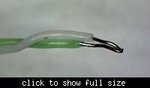
We wish to attach the attached type of thermocouple to our mosfet cases so as to measure the temperature of the FET case. Please recommend a cost-effective glue for this?
We were also wondering about just using kapton tape to stick the thermocouple end to the fet case….and just squirting some thermal paste over the thermocouple end before the kapton tape is applied so as to give better thermal coupling of the thermocouple junction to the fet case.
What do you recommend for thermocouple attachement to FET cases? We realise a glued thermocouple end cannot be re-used, ..it has to be cut off and the PTFE shield has to be stripped back so that another thermocouple junction can be made, leaving the overall thermocouple wire length shorter.
 

Attachments

  • Thermocouple.jpg
    Thermocouple.jpg
    3.5 KB · Views: 245

JB-Weld (any North American hardware, home or auto
supply store) will take a fair bit of heat, is tough and
sticks to about anything but polyethylene and Delrin.
Downside is a long setup time. There's a quick-set
version now which is inferior mechanically.

And why can you not reuse a glued end? It's not
conductive or anything like that. I'd bet a dip in
paint stripper overnight would take the glue right
off anyway, without touching the metal. Then an
acetone clean to take off silicone residue, and
there you go.
 
  • Like
Reactions: treez

    T

    Points: 2
    Helpful Answer Positive Rating
Use the thinnest wire thermocouple and use ANY rapid setting glue.

Using a tape on top of this is not recommended because you want the case temp in free air (I guess). Temp will be higher if you put a tape on.

If you want to use thermal paste you should use hardware to press the wire tightly.

If you heat it, the glue will burn off and the thermocouple can be reused (what is the thermocouple wire material you are using?)
 

To measure semiconductor temperature, I've seen regulatory agencies UL/CSA use fine-wire thermocouples glued down with cyanoacrylate adhesive, like Henkel Loctite 382 with 7452 accelerator.

In practice, the thermocouple wire acts a tiny heatsink you lose some heat due to it, a few degrees off.
Convection air currents in the test area matter, I usually cover it or away from air-con ducts.
 

In practice, the thermocouple wire acts a tiny heatsink you lose some heat due to it, a few degrees off....

I do not have a reference in hand, but I would say that if you use thin wires (say 0.2-0.3mm dia or around that) and you are going to measure the temp of a FET case, the error may be order of a few tenth of a degree off...

Well within the measurement errors of thermocouples (usually +/-1C)
 

No, you forget the thermal resistance of the glue.
That, and the conduction heat loss through the thermocouple wire can give several degrees (low) error.

But case temperature is not as meaningful as the semiconductor's junction temperature, so you add in RθJC or ΨJT, junction-to-case or top-of-case.

I compare with thermal imaging camera measurements and it depends on the size of the semiconductor, delta T over ambient and other factors. TI goes into more depth here SPRA953C
 

Hi,

What are you trying to achieve?
Gives measuring the FET plastic case temperature really good information?
The datasheet value of thermal resistance "junction to case" is not junction to plastic case, it is junction to matal piece of the case, that is mounted to a heatsink.

Are you interested in:
* plastic case temperature
* temperature of metal piece of the case
* or junction temperature?

Klaus
 

I support Klaus's question.

What FET package are you measuring? The plastic body is not the best place but to measure from a metal tab or heatsink requires electrical isolation. The mV output of the thermocouple is insignificant compared to the conducted voltages likely to be found between thermocouple wires and almost anywhere else in a circuit, especially in a power application where even ground voltages are significant at high currents.

Do you have to use a thermocouple? Over the operating temperature range of most FETs, there are more sensitive devices, thermistors for example, that are already electrically isolated and avoid cold junction compensation and connector problems.

Brian.
 

I would use thermocouple if thermal imaging isn't an option.

Thin thermocouple wire is suggested for low measurement error. Omega has PFA insulated wire starting from 0.08 mm.

Useful attachment options depend on the measurement situation, e.g. surface mount package, conventional package with or without heat sink.
 

For SMD parts without heat sink, I would tape the thermocouple to the package top.

Consider that junction temperature may be considerable above package top due to the package material thermal resistance.
 
  • Like
Reactions: treez

    T

    Points: 2
    Helpful Answer Positive Rating
Hello,
There is not a single Type J,K,E or T type thermocouple wire in stock in Farnell UK.
Do you know of a vendor of cheap thermocouple wires of those types?
We need at least 2 metre lengths so we can draw it out of the thermal chamber and into the thermocouple reader.
The thermocouple wire needs to be supple, like the green & white type in the picture of the top post.
Also, What’s your opinion on soldering metre lengths of thermocouple wire together so as to make it longer? (As you know, we do not want to waste thermocouple wire as it is hideously expensive).
We only need accuracy say +/- 4 degreesC

- - - Updated - - -

This thermocouple wire....
**broken link removed**
...says its type "KX" but we have never heard of that, do you know what it is?

- - - Updated - - -

Or, to extend a k type thermocouple wire, do you think we would be better off using sockets/connectors like the following?......

K type Socket:
**broken link removed**

K type plug:
**broken link removed**

- - - Updated - - -

For SMD parts without heat sink, I would tape the thermocouple to the package top.
Thanks, and i presume you mean using Kapton tape?, as no other (reasonably priced) tape can remain sticky at temperatures up to 150degC?

- - - Updated - - -

We believe we should use this glue to glue the thermocouple to the IC/FET case surface…

Superglue…£2.80
**broken link removed**

We will use this cheapest (£8.98) activator to immediately harden the glue…
**broken link removed**

…we admit that the thermopcouple junction, when glued to the IC/FET, may end up being 0.3mm or so above the actual IC/FET case surface, but we doubt there will be more then 5 degrees dropped across such a small “glue gap”?

- - - Updated - - -

I must admit, we are looking for the cheapest superglue, and the cheapest activator which will immediately (within a few 10’s of seconds) cure it….but the entire Loctite website does not allow you to find what this combination is….Do you know it?

https://www.loctiteproducts.com/epoxies.shtml#multi-purpose

We must have the glue and the activator in separate tubes/bottles because otherwise you just end up with the applicator nozzle getting jammed.
 

You can use about 2-3 inches of the thermocouple wire and then connect it with regular copper wire. I recommend you spot weld the wire rather than solder (theoretically it does not matter) and you should use the extension wire from the same roll.

If you are looking for +/- 4C, then why you are so worried? A glass thermometer measures your body temp within 0.1C (or better) with a relatively thick glass bulb within a couple of minutes is a regular measurement.

The clinical thermometer can be used on the armpit, in the mouth or in the anus (the variations are small) but the results are considered reliable.
 

You can use about 2-3 inches of the thermocouple wire and then connect it with regular copper wire.
Thanks, this is groundbreaking to me.
Its a way of dramatically reducing the cost of thermocouple measurments.
You just use 3 inches of thermocouple wire, and then for the other 2 metres, you just have it soldered to some twisted pair copper wires...and take it back to the thermopcouple reader like that. Are you sure? It sounds to good to be true
 

Hi,

There are a lot differences between a body thermometer and a type K thermocouple.
* the body thermometer is optimized for a very narrow temperature range, the thermocouple for avery wide range.
* the body thermometer is an absolute temperature measurement, the thermocouple is a relative measurement.
* the body thermometer has a relatively large thermal conductivity area, the thermocouple a very small
* the body thermometer is surrounded over a length of some centimeters with the same temperature, the thermocouple not.

A simple diode has a tempco of about -2mV/°C, it is easily stackable and can be used for absolute temperature measurement.
A type K thermocouple has a tempco of about 40uV/°C and it measures the temperature relative to the cold junction temperature.

In a power IC without dedicated temperature measurement I "misused" the protection diode of a (static) digital input to measure the die temperature. Works great. Very fast and as close as possible at the source of heat.

Klaus
 
  • Like
Reactions: mtwieg

    mtwieg

    Points: 2
    Helpful Answer Positive Rating
In a power IC without dedicated temperature measurement I "misused" the protection diode of a (static) digital input to measure the die temperature. Works great. Very fast and as close as possible at the source of heat.
Stealing this, thanks.
 
  • Like
Reactions: treez

    T

    Points: 2
    Helpful Answer Positive Rating
Thermocouples are accurate, the connections to them can cause all kinds of problems. Observe what c_mitra tells you about the extension wire and how to join it. The reason is simple, a thermocouple junction produces a tiny voltage because the two metals are directly joined (spot welded or melted together). If you add further joints using dissimilar metals, copper for example, those junctions also produce a voltage and being in a different location the voltage may be some way away from the place you want to measure. Adding solder to the equation makes matters even worse as more metals are involved. This is why special plugs are used on many thermocouple probes, it's to minimize the transitions from one type of metal to another and to use metal types that introduce least heat derived voltage.

Also note the comments about cold junction compensation although this is usually performed with predictable reference voltages rather than a bucket of ice these days!

As you are only looking for +/- 4C accuracy and self heating isn't an issue, I would still consider a thermistor. They are not particularly accurate from one batch to another but variations are fairly small (within 5% of resistance) and it only takes a moment to calibrate the errors/differences out and you can use long extension wires. Just converting a resistance to a temperature is easy compared to amplifying and offsetting microvolt readings.

A silicon diode has about 50 times more Vf/C than a thermocouple and if you use an SMD package with a flat top you can tape it "face to face" to the body of your test device, maybe using a tiny dot of heat sink compound to improve heat transfer. Again, you can use a simple voltmeter to take a reading you can then convert to Celsius.

Brian.
 
  • Like
Reactions: treez

    T

    Points: 2
    Helpful Answer Positive Rating
You just use 3 inches of thermocouple wire, and then for the other 2 metres, you just have it soldered to some twisted pair copper wires...and take it back to the thermopcouple reader like that. Are you sure? It sounds to good to be true

Your measurement can be many meters away from the point of measurement. Only condition is that the point where you join the Cu wire must be at same temp (so that they cancel out exactly). This is a very common practice.

- - - Updated - - -

* the body thermometer is optimized for a very narrow temperature range, the thermocouple for a very wide range.

There is no special optimization, to the best of my knowledge and belief, compared to a regular mercury thermometer that works from -20 to 350C without fuss.

* the body thermometer is an absolute temperature measurement, the thermocouple is a relative measurement.
Sorry, no. Common Hg thermometers need two point calibration. For common use, the two fixed points used are the melting point and the boiling point of water.
* the body thermometer has a relatively large thermal conductivity area, the thermocouple a very small
Even though the glass is highly insulating (thermally) and the temp diff is rather small, the thermometer reports temp rather promptly. A thermocouple needs very little heat to get the temp of the object. Like we do not use thermal grease with clinical thermometers, we need not worry about a nanoliter of glue used to stick the thermocouple.
* the body thermometer is surrounded over a length of some centimeters with the same temperature, the thermocouple not.
The bulb of the thermometer must be at the same temp of the patient; the same condition must be used for the thermocouple junction point.

A simple diode has a tempco of about -2mV/°C, it is easily stackable and can be used for absolute temperature measurement.
A type K thermocouple has a tempco of about 40uV/°C and it measures the temperature relative to the cold junction temperature.

True. But neither has a linear response.
 

Hi,

* the body thermometer is an absolute temperature measurement, the thermocouple is a relative measurement.
Sorry, no. Common Hg thermometers need two point calibration. For common use, the two fixed points used are the melting point and the boiling point of water.
This has nothing to do with calibration.
With a thermometer you have one temperature sensitive point.
With a thermocouple you have two about (because of unlinearity) equally temperature sensitive points, the hot junction and the cold junction.
A thermocouple system measures the difference between these two points. It measures the temperature of the hot junction relative to the temperature of the cold junction.
If you want to build an absolute temperature thermometer with an thermocouple you need to know the absolute temperature of the cold junction.
This can be ice water (known as 0°C) or you need an additional absolute temperature sensor and add it's temperature to the measurement of the thermocouple.

Klaus
 

Status
Not open for further replies.

Similar threads

Part and Inventory Search

Welcome to EDABoard.com

Sponsor

Back
Top