flyingoven
Newbie level 6
Hi!
I want to simulate S-parameters for measuring Teflon by T/R method, and choose rectangular waveguide WR75 for measurement.
Then using NRW method to obtain permittivity and permeability from simulating S-parameters.
First assume TE10 is dominant mode, cutoff frequency is 7.87GHz and cutoff wavelength is 0.0381m.
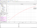
I created a box of Teflon(a = 19.05mm, b = 9.525mm, L = 20mm) in HFss below:

In figure Port1 is shown, the opposite face is set as port2, other faces are set as Perfect E boundrary.
Other setting In HFSS:
Solutin Type:
Modal, Network Analysis
In wave Port:
Number of modes : 1
Integrationline : None
Analysis Setup:
Solution Frequenct : 18GHz
Frequency Sweep:
Start : 10GHz
Stop : 15GHz
Step Size : 5MHz
Swep Type : Discrete
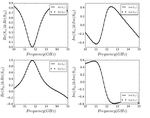
Then exported S-parameters(normalized to 50 ohms) from HFSS, the S-parameters from data is shown below:

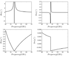
And use NRW method(cutoff wavelength is 0.0381mm), the result:

Apparently, the result is not correct, relative permittivity for Teflon is 2.1, relative permeability is 1.
I'm not sure which part was wrong.
Hope someone could help me!
Thanks!
I want to simulate S-parameters for measuring Teflon by T/R method, and choose rectangular waveguide WR75 for measurement.
Then using NRW method to obtain permittivity and permeability from simulating S-parameters.
First assume TE10 is dominant mode, cutoff frequency is 7.87GHz and cutoff wavelength is 0.0381m.
I created a box of Teflon(a = 19.05mm, b = 9.525mm, L = 20mm) in HFss below:

In figure Port1 is shown, the opposite face is set as port2, other faces are set as Perfect E boundrary.
Other setting In HFSS:
Solutin Type:
Modal, Network Analysis
In wave Port:
Number of modes : 1
Integrationline : None
Analysis Setup:
Solution Frequenct : 18GHz
Frequency Sweep:
Start : 10GHz
Stop : 15GHz
Step Size : 5MHz
Swep Type : Discrete
Then exported S-parameters(normalized to 50 ohms) from HFSS, the S-parameters from data is shown below:

And use NRW method(cutoff wavelength is 0.0381mm), the result:

Apparently, the result is not correct, relative permittivity for Teflon is 2.1, relative permeability is 1.
I'm not sure which part was wrong.
Hope someone could help me!
Thanks!

