Continue to Site

Welcome to EDAboard.com

Welcome to our site! EDAboard.com is an international Electronics Discussion Forum focused on EDA software, circuits, schematics, books, theory, papers, asic, pld, 8051, DSP, Network, RF, Analog Design, PCB, Service Manuals... and a whole lot more! To participate you need to register. Registration is free. Click here to register now.

Sony bravia 32bx350 wont power on after going off, pls help!!!! Couyld it be the pcb?

Status
Not open for further replies.

psy

Newbie level 3
Joined
Jun 1, 2017
Messages
4
Helped
0
Reputation
0
Reaction score
0
Trophy points
1
Activity points
28
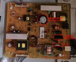
IMG_20161123_153839.jpg
what must be done to fix it:?:
 

"could it be the PCB?" is like saying my car doesn't start, could it be the engine?

PCBs are just the mounting method of the components, you can change a whole board but almost certainly only one of the components is responsible for the fault.
The usual failure is the electrolytic capacitors, thankfully, they are easy to source and not too expensive, certainly they cost far less than a whole PCB.
They are the round metal cylinders with brown or black plastic sleeves around them and a "Y" pattern pressed into their metal tops. I would replace them all on the lower board, there are only a few and they do degrade over time anyway so using new ones will make it more reliable for the future.

The top board is probably OK.

Of course I can't be certain without seeing it myself but there is a good chance I'm right. Replace them with ones of the same value, voltage rating and temperature rating although the manufacturers name is not important. If you can, use ones with "low ESR" as they will last longer.

Brian.
 

Hello psy,
If your device won't power up what-so-ever, then you need to check the main fuse to see if it has blown (See attachment).
You're going to need the aid of a multi-meter. If you don't own one then it will be virtually impossible to diagnose the fault
via pictures. Readings are needed to see what component/s are at fault.
If you do have a multi-meter, then set it to read low ohms and measure across the fuse to see if it is open circuit. But make sure
you DON'T have the power connected.
Before you start, make sure you discharge the main filter capacitor. You can identify the capacitor via the attachment. You can use
a screwdriver with an insulated handle across its two leads on the copper side of the board.
Now you can check the fuse and if you find that its a virtual short circuit, then the fuse is in tact and the problem lies elsewhere.
If the fuse is open circuit, then you need to check across the main filter capacitor. Same again, using your multi-meter selected for
low ohms, measure across the main filter capacitor leads. You may notice that it will start with low ohms, then it should build up to
an almost open circuit.
If you're getting a virtual short, then there's a good chance that the bridge rectifier has a short/s between its leads and would need to be replaced.
Can you please check what I've already suggested and let us know what you've found. We can then try to point you further.
Good luck.
Regards,
Relayer

Sony01.jpg
 

Hello psy,
If your device won't power up what-so-ever, then you need to check the main fuse to see if it has blown (See attachment).
You're going to need the aid of a multi-meter. If you don't own one then it will be virtually impossible to diagnose the fault
via pictures. Readings are needed to see what component/s are at fault.
If you do have a multi-meter, then set it to read low ohms and measure across the fuse to see if it is open circuit. But make sure
you DON'T have the power connected.
Before you start, make sure you discharge the main filter capacitor. You can identify the capacitor via the attachment. You can use
a screwdriver with an insulated handle across its two leads on the copper side of the board.
Now you can check the fuse and if you find that its a virtual short circuit, then the fuse is in tact and the problem lies elsewhere.
If the fuse is open circuit, then you need to check across the main filter capacitor. Same again, using your multi-meter selected for
low ohms, measure across the main filter capacitor leads. You may notice that it will start with low ohms, then it should build up to
an almost open circuit.
If you're getting a virtual short, then there's a good chance that the bridge rectifier has a short/s between its leads and would need to be replaced.
Can you please check what I've already suggested and let us know what you've found. We can then try to point you further.
Good luck.
Regards,
Relayer

View attachment 139129
dear relayer,I appreciate this immensely and I'm glad I joined the edaboard community. Cheers. I'll do as said and send feedback with results. I hope it comes out positive.
 

DIODE OLD AND NEW.jpgTRACED.jpgTRACED.jpg

hears the possible cause of the problem as revealed in the photo. now, should i use the new components (Diodes) with those values? pls, confirm before i proceed to unsolder and replace with the new. Thanks!
 

It COULD be those but diodes are generally very reliable. It is far more likely to be capacitors causing your problem. If you already have the replacements then try them but I doubt it will fix the problem.

Brian.
 

    V

    Points: 2
    Helpful Answer Positive Rating
Hello psy,
Did you do the checks that I asked you to do?
Before you replace those high current diodes, you really need to check the old ones.
Please take a look at the following tutorial I wrote some time ago on another Forum: HERE
Scroll down the page until you come to the section to check diodes.
The old and new diodes are common cathode types.
I realize you are not keen to de-solder the old diodes, as they are set in place with rivets, and are difficult to remove. But to obtain accurate readings you would need to de-solder the cathode
then take your measurements and compare them with the new ones. The readings between the old and the new may differ slightly, but as long as there are no shorts or leakage, they should be serviceable
and don't need to be replaced.
You can check the old diodes in circuit before de-soldering and removing them, once again you should obtain readings similar to the new ones, but if you don't, then it is possible that other
components within the circuit common to the diodes may effect your readings.
Since those high current diodes are of the schottky type, your forward bias readings could go as low as 0.200. But as I said, comparison between old and new should give you a clue.
You should ensure that you perform a punch-through test to be certain there is no reverse leakage.
When ever you trouble shoot a circuit, you MUST eliminate ALL the likely suspects as being faulty, then delve deeper into other components less
likely to be the problem.
Please let us know how you get on.
Regards,
Relayer
 

    V

    Points: 2
    Helpful Answer Positive Rating
Status
Not open for further replies.

Part and Inventory Search

Welcome to EDABoard.com

Sponsor

Back
Top