Continue to Site

Welcome to EDAboard.com

Welcome to our site! EDAboard.com is an international Electronics Discussion Forum focused on EDA software, circuits, schematics, books, theory, papers, asic, pld, 8051, DSP, Network, RF, Analog Design, PCB, Service Manuals... and a whole lot more! To participate you need to register. Registration is free. Click here to register now.

Giving an input DC bias current for an IC

Status
Not open for further replies.

venn_ng

Member level 5
Joined
Mar 26, 2017
Messages
87
Helped
1
Reputation
2
Reaction score
1
Trophy points
18
Activity points
645
Hi,

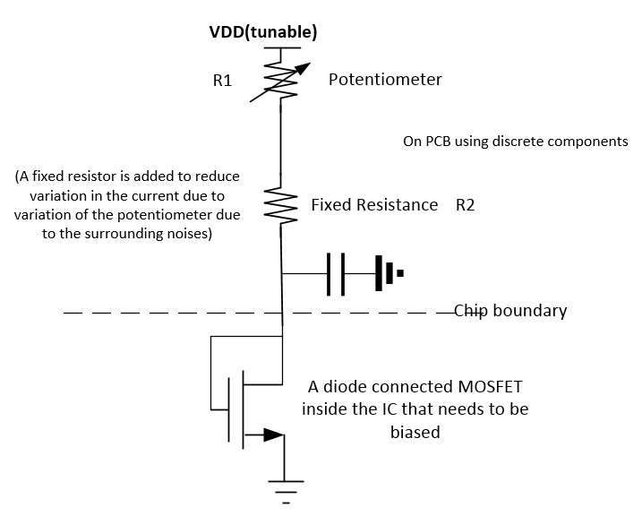
I am trying to give the DC bias current to an IC from an external source. The way I am generating this current is by using a potentiometer structure shown below.


By changing both VDD (tunable) and R1 (potentiometer), I can change the current. The VDD comes from an LDO and hence it's kind of accurate.

The thing is I placed another series resistor R2 to reduce the variations in the current due to possible variations in the potentiometer, as I heard potentiometers are very sensitive to their environments and tend to change with time a lot.

My quesiton is if I keep R2 like 25% of R1, would it be good enough? Also, is this a good way of generating current externally for biasing circuits inside an IC?

Thanks in advance
 

If you decouple it as shown, you are not providing a
DC bias current, but a DC plus any ground bounce that
may come in between cap return and on-chip ground.
Depending on what else is going on, this could be a
big noise injector (and not nice white noise, but maybe
synchronous, maybe prone to self-oscillate if the phase
is just right (wrong)). Put a vsin source in the ground
leg of the cap and look at your ground noise gain (with
as much realism regarding the chip ground branch as
you can come up with).

Resistor R2 ought to be the value that would set the
maximum current of interest, and then R1_max+R2 should
be selected to deliver the minimum.

I get it..Do you know any other better way?
 

Resistor feed is fine, provided that you have a good
voltage source tolerance, can stand the variation in
the "pilot" FET and so on. Simplicity often wins.

But if you -need- the current to be a particular,
accurate value (without re-twiddling the pot every
time somebody exhales) then a current source bias
might be preferable. Harder to come by than a resistor.

A higher voltage source, higher resistor value will
reduce the influence of make (process) and temperature
variations on the current taken by the pilot FET. You
can assume the FET will still hold itself down (limit it if
you feel shy) against a nominally-same current.

If you are concerned about wiper skip, noise while
adjusting, microphonics etc. you might put the pot
in shunt across a fixed R1 (or pot + series R1, in
parallel with R2) etc; you can get to a min and max
limit that remains sane with pot open / shorted.

I have myself used the resistor scheme similar to
shown, just for simplicity's sake. Other than, not
using the pin connected shunt cap (as this is an
AC short and for current-source-like you want an
AC open, infinite Z, or tolerable approximation).

Hi. Thanks for the reply. I thought I would use a ac shunt to ground to filter out the noise due to potentiometer resistance and fixed resistance. Also it would get rid of variations due to potentiometer, but I get your concern about ground bounce
 

Resistor feed is fine, provided that you have a good
voltage source tolerance, can stand the variation in
the "pilot" FET and so on. Simplicity often wins.

But if you -need- the current to be a particular,
accurate value (without re-twiddling the pot every
time somebody exhales) then a current source bias
might be preferable. Harder to come by than a resistor.

A higher voltage source, higher resistor value will
reduce the influence of make (process) and temperature
variations on the current taken by the pilot FET. You
can assume the FET will still hold itself down (limit it if
you feel shy) against a nominally-same current.

If you are concerned about wiper skip, noise while
adjusting, microphonics etc. you might put the pot
in shunt across a fixed R1 (or pot + series R1, in
parallel with R2) etc; you can get to a min and max
limit that remains sane with pot open / shorted.

I have myself used the resistor scheme similar to
shown, just for simplicity's sake. Other than, not
using the pin connected shunt cap (as this is an
AC short and for current-source-like you want an
AC open, infinite Z, or tolerable approximation).

Hi

I am planning to use this IC for generating the current source
**broken link removed**
Do you think this might solve the issues that we talked about before?
 

Status
Not open for further replies.

Part and Inventory Search

Welcome to EDABoard.com

Sponsor

Back
Top