Continue to Site

Welcome to EDAboard.com

Welcome to our site! EDAboard.com is an international Electronics Discussion Forum focused on EDA software, circuits, schematics, books, theory, papers, asic, pld, 8051, DSP, Network, RF, Analog Design, PCB, Service Manuals... and a whole lot more! To participate you need to register. Registration is free. Click here to register now.

[SOLVED] [Moved]: Frequency Response Heterojunction Bipolar Transistor

Status
Not open for further replies.

insyspower

Newbie level 6
Joined
Aug 5, 2016
Messages
13
Helped
0
Reputation
0
Reaction score
0
Trophy points
1
Activity points
169
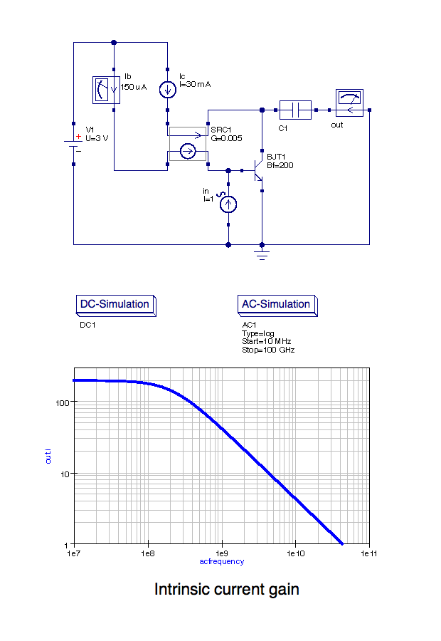
I have a project, first i need to find a circuit to Analyse/study the Frequency Response of Heterojunction Bipolar Transistor. Then simulate that circuit on SPICE (i'am using Orcad Cadence).

Can someone help me finding a circuit as mentioned above, I'm having difficulties finding one. Any links, etc, would be very helpful, just need some circuit to start with.
 

Have you already got a SPICE model of an HBT? Which application do you want to simulate? Voltage gain, current gain? In any Analog Circuit Design textbook you can find corresponding circuits. Search for intrinsic gain, e.g.
 
I believe Georgia Tech had done some work in SiGe HBT
logic circuits (looking at single event upset sensitivities)
which might give you a digital-ish thing to work with.
Outside of that you'd be looking at RF stuff. Foundry
PDKs are where you'd likely find models, and for RF they
tend to be pretty elaborate and OrCAD SPICE may not
be up to date with the more exotic (Spectre, yes; but
what comes with OrCAD?).

SiGe technology at one foundry ranges over several
octaves of fT. I'm not imagining what about the
frequency response you need to "study". It is what
it is; are you after anything more than representing
a S-param pad cage's impedances and pulling a
realistic-enough-for-an-"A" fT vs Ic curve, or something?
 
Thanks for the help, i already got a SPICE model of an HBT, infinion have some models:
https://design.infineon.com/tinadem...s|RF front-end|LNA|&file=rf_BFP640F_AN179.TSC

I want to use Orcad cadence but might change to another app, if Orcad not up for the task.
Couldn't find any circuit in that Analog Circuit Design textbooks, i have checked the first 4 books.
dB Magnitude of Voltage, Intrinsic Gain is what i want to Study. (Frequency vs Gain(dB) chart/graph).
Georgia Tech - J.D. Cressler and G.Niu, Silicon-Germanium Heterojunction Bipolar Transistors Book might be the book i' am looking for, but is not free book, i have to pay a lot to see the content.

The fT (Transition frequency) of a transistor (the ones i'm studying) ranges from 10 GHz to 100 GHz (High Frequency).
The Beta should be around β=200 (Hfe).

Still looking for a complete circuit as mentioned above, if someone can find a circuit other than infinion.
 

Still looking for a complete circuit as mentioned above, if someone can find a circuit other than infinion.

Here I've sketched my own intrinsic gain simulation schematic:

As a BJT essentially is a current gain device, I've chosen the current gain ac analysis - but you could similarly set up for an ac voltage gain characteristic.
In the above simulation, the -3dB decay point is about 350 MHz, whereas the transit frequency fT for the intrinsic current gain here is around 40 GHz (BJT parameters so chosen).

The simulation result of course depends on the chosen operation point parameters, here Vds and Ic . Depending on the DC forward current gain Bf (= low frequency β = hfe), I've used a CCCS (G=1/Bf) to adjust the DC base current accordingly. DC operation point adjustment and ac input and output current are totally independent of each other.

May be you can draw & simulate such a circuit directly with the Network Analysis program of the Infineon Designer tool.
Have fun!
 
Thanks that helps.
i need to draw and simulate on SPICE, and also need the model of TBH and a library. (.lib,.olb and .sch files)
i have been told to use a circuit not from infineon.
 

Where i can buy cheap BFP640F Transistors, i need at least 5 transistors, at maximun i buy 10 or 20.
Maybe is a dumb question, but in my circuit i have some PNP transistors BJT and the BFP640F is NPN !!!, i have to build that circuit in a breadboard and Determine Vout, Vin, Gain, etc. i have to replace the BJT PNP with the BFP640F but this transistor is NPN, how i do connect them in a breadboard, the emitter is reversed !!!
 

OrCAD is not a proper simulator for high frequencies.I recommend AWR MWOffice or Keysight ADS.Cadence Spectre is also very suitable but the model can create some issues.
Infineon releases accurate models and Design Kits for both simulators.
 
i want to simulate the circuit AmpopTBH2 on PSpice.
On image 1hbt.png we can see that Draft4 is working fine, on image 2hbt_pardif.png is the same circuit as Draft4 but on PSpice that circuit won't work right, because on Green voltage marker the same point as vpardif on LTspice, the voltage is always 3V (3vpardif_pspice.png)
The transistor i am using is BFR92A/PLP, because on PHILRF.lib the BFR92 is not there, no model available, but BFR92A is still the complementary of BFT92 so i thought it would work on PSpice, but unfortunately yet no.

The only circuit of HBT on PSpice is working right now for me is Class B Amplifier: HBTclassB.png & HBTclassB_vout_graph.png . 1hbt.png
2hbt_pardif.png3vpardif_pspice.pngHBTclassB.pngHBTclassB_vout_graph.png
 

Study Differential Amplifier Concept.You circuit has no Base bias, no tail current, ..
Look at practical examples,search tutorials,work hard buddy..
 
The fix was simple, but took me a while to figure out, the problem was the library or PSpice had the Base and Emitter interchanged.
Now i have other problem, some library have encrypted models, my PSpice is 16.6 Lite, i'am not allowed to change simulator.
 

OP asked to "forget" this post:

When i Run the PSpice Circuit i got the following error and warning:
INFO(ORCAP-2191): Creating PSpice Netlist
INFO(ORNET-1041): Writing PSpice Flat Netlist C:\CADENCE\SPB_16.6\TOOLS\CAPTURE\pcb3-PSpiceFiles\SCHEMATIC1\SCHEMATIC1.net
ERROR(ORNET-1111): PSpiceTemplate syntax error %s Unexpected end of string
WARNING(ORNET-1119): No PSpiceTemplate for J1, ignoring

How i can fix this error and warning?
 
Last edited by a moderator:

Status
Not open for further replies.

Part and Inventory Search

Welcome to EDABoard.com

Sponsor

Back
Top