Continue to Site

Welcome to EDAboard.com

Welcome to our site! EDAboard.com is an international Electronics Discussion Forum focused on EDA software, circuits, schematics, books, theory, papers, asic, pld, 8051, DSP, Network, RF, Analog Design, PCB, Service Manuals... and a whole lot more! To participate you need to register. Registration is free. Click here to register now.

A question on pulse to square-wave conversion for a given frequency range

Status
Not open for further replies.

doncarlosalbatros

Full Member level 2
Joined
Nov 26, 2016
Messages
143
Helped
1
Reputation
2
Reaction score
1
Trophy points
18
Activity points
1,758
As a stage of a circuit I have 0...5V amplitude pulse train coming from the output of a 74hc74.
The pulse train's frequency varies from 50Hz upto 1kHz.

I want pulse train to be converted to a -2.5V to +2.5V squarewave for at any freq. between 50Hz to 1kHz.

My aim is, after I obtain the +/-2.5V square wave, I will scale it to a +-10mV square wave by a voltage divider.

I will send this to a smartphone mic jack.

I hesitate to use a blocking cap because of two reasons:

1-) The frequency of the pulse to be converted is not fixed so a fixed cap may not work in desired freq. range
2-) The cap might interact with the inner circuitry(input impedance of the smartphone pre-amp)

So I was thinking there might be an IC solution to convert 0..5V pulse to +/-2.5V square wave(or any amplitude square wave). How can I achieve that? A circuit suggestion would help a lot.
 

1-) The frequency of the pulse to be converted is not fixed so a fixed cap may not work in desired freq. range
2-) The cap might interact with the inner circuitry(input impedance of the smartphone pre-amp)
1) is not a problem here because the cap is used to block the DC and pass the remaining frequencies. Indeed, the problem could be the 2nd point you are commenting.

One possible solution would be to send this 0-5 V pulse train to a adder circuit (with OP Amp) which would add that with a -2.5 V.
 

CataM can you show me an example diagram? I dont want to use a split power supply. I will only use a single supply in the whole circuit. Can an Opamp adder subtract 2.5V ?
 

Does the pre-amp have a HPF at the input ?

I cannot say anything because Samsung and Apple does not provide inner circuitry data for mic input. But my guess is the some 1.5 to 2V bias voltage come out from mic when I measure and I think they have already have AC coupling capacitor inside. Do you mean maybe I dont need AC coupling?? Should I just send 0..20mV pulses to the mic jack?
 

Can an Opamp adder subtract 2.5V ?
Yes. A difference amplifier then with unity gain but this option is out because you are not using a split power supply.
 

Hi,

I don't agree with both statements of post#1.
--> A C-R-R is a simple solution to generate +/-10mV from a 0V/5V square wave.
And if the time constant is big enough you won't get big distortions.

A "difference amplifier" is the more difficult solution.
But the problem is how to get the square wave, I assume you mean precise 50% duty cycle?

Klaus
 

--> A C-R-R is a simple solution to generate +/-10mV from a 0V/5V square wave.
And if the time constant is big enough you won't get big distortions.
Probably you meant "low enough".
A "difference amplifier" is the more difficult solution.
I do not think a difference amplifier implemented with 1 single OP Amp is very difficult... indeed, more difficult than a simple passive CRR network.
 

An RC coupling would seem to do the job, but the OP hasn't clarified if the pulses come in a continuous train or in short bursts, and whether he needs perfect square waves - well, nearly perfect anyway.

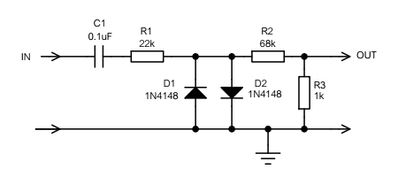
An RC time constant that's large enough to pass the lower frequencies without severe distortion will take time to settle down. If the pulses are in short bursts, this could pose a problem. One possible solution is to clamp the output of the RC coupling with two reverse parallel diodes.
 

Hi,

Probably you meant "low enough".
No. Time constant is R x C. And one needs a big time constant for low distortion of the signal of interest (50...1000Hz).

I do not think a difference amplifier implemented with 1 single OP Amp is very difficult... indeed, more difficult than a simple passive CRR network.
...and don't forget the negative power supply..

One possible solution is to clamp the output of the RC coupling with two reverse parallel diodes.
Good idea.

Klaus
 

I dont get what you mean. Do you mean AC coupling 0..5V pulse train and then use two reverse parallel diodes. Diodes can only clamp to 700mV. I need 10mV. Please could you draw what you mean if possible? thanks

- - - Updated - - -

pulse train from 74hc74 is continuous with around 50% duty cycle
 

You can simply reduce the amplitude of the clamped waveform with a voltage divider, which was your original intention anyway. Here's the circuit:

2500965700_1496035484.png
 

Status
Not open for further replies.

Part and Inventory Search

Welcome to EDABoard.com

Sponsor

Back
Top