Continue to Site

Welcome to EDAboard.com

Welcome to our site! EDAboard.com is an international Electronics Discussion Forum focused on EDA software, circuits, schematics, books, theory, papers, asic, pld, 8051, DSP, Network, RF, Analog Design, PCB, Service Manuals... and a whole lot more! To participate you need to register. Registration is free. Click here to register now.

Relay connection with Dimmer

Status
Not open for further replies.

ishtiaqshaheer

Junior Member level 3
Joined
Mar 17, 2017
Messages
26
Helped
0
Reputation
0
Reaction score
0
Trophy points
1
Location
India
Activity points
203
Hi,I'm making a PCB where I should connect my Dimmer module to Relay so that I can ON/OFF the dimmer using relay and even control the dimming.
Now I'm getting a problem where my dimming is happening even when Relay is OFF
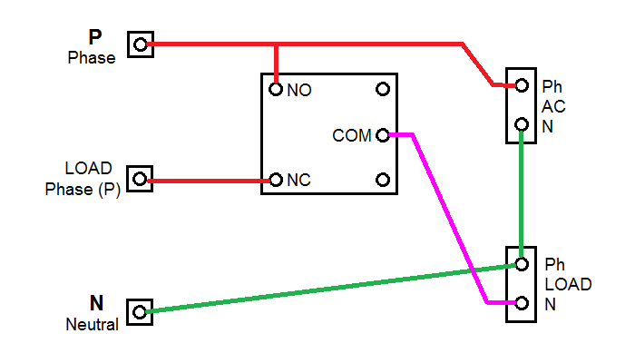
These are my connections, please help me through this connections if wrong. (On the right side its Dimmer connections and on left I've 3 Terminal blocks which will be connected to Relay & Dimmer module)

IMG_20170525_122217.jpg
 

You have connected COM and NC relays contacts, so by design the circuit is active with unpowered relays.

If you won't opposite relays action, connect COM and NO. If that's neither your intention, clarify the expected circuit operation.
 

If you won't opposite relays action, connect COM and NO. If that's neither your intention, clarify the expected circuit operation.

Thanks for the reply
I've connected to "NO" too but when I've done this the circuit wasn't working. Even I'm unable to understand the reason why it isn't working
Not only that relay connection but the other relay connections of my board are also not working when I connect it to "NO"
Help me with this question too :)

The circuit operation goes like this: When you give an input saying the relay should be ON then relay should ON and when you give the dim should be 50% then it should Dim to 50% (similarly other values)
And what's happening is the dimming is working without relay being ON/OFF condition
 
Last edited:

Hello Everyone,
any other ideas how to connect the dimmer to the Relay (according to my given circuit)
Thanks in advance
 

I'm still not perfectly clear what you're trying to do. Here's one possible circuit, drawn in your style, and this is what it does:

- When the relay is OFF, the dimmer will control the load.
- When the relay is ON, it bypasses the dimmer and the load will receive full power. That is, the dimmer will have no effect.

Is this what you want?

Edit: Correction - I made a mistake in naming the load terminals. Phase and neutral should be reversed in the drawing - just the names, not the connections.

 
Last edited:

The circuit operation goes like this:
Input:Dim On > The Relay connected to dimmer should ON and the load should be at full power
Input:Dim 50 > The load should Dim to level 50 (half the power to load)
Input:Dim Off > The Relay & load should OFF

What's happening according to my circuit is, even if the relay is OFF and when the input is given as "Dim 50" the Load is getting to 50(without depending on Relay switching)

So I need a circuit where the load dimming & ON/OFF should be controlled using Relay ON/OFF

- - - Updated - - -

- When the relay is ON, it bypasses the dimmer and the load will receive full power. That is, the dimmer will have no effect.

If relay is ON then the Phase(P) will be passing to AC(P) and to Load(P) as NO is connected to AC(P) & COM is connected to Load(P), will this Phase from both sides(AC & Load) of Dimmer will not damage the circuit of Dimmer?
 

I'm still not perfectly clear what you're trying to do. Here's one possible circuit, drawn in your style, and this is what it does:

- When the relay is OFF, the dimmer will control the load.
- When the relay is ON, it bypasses the dimmer and the load will receive full power. That is, the dimmer will have no effect.

Is this what you want?

Edit: Correction - I made a mistake in naming the load terminals. Phase and neutral should be reversed in the drawing - just the names, not the connections.


Hi #Pjdd
I've tried your circuit and even here the same thing is going on, without the relay being ON the dim level can be set to 50 or any value(similar to what's happening in my circuit)
 

All right, if that's not it, then you need to provide more details.

What type of dimmer are you using?
Those three terminals on the left side of the drawing: are they terminals on the dimmer module?
What exactly are Input: Dim On/50/Off ? Are they MCU commands?
What is supposed to drive the relay? Not just when it has to be on or off. What makes it turn on or off? A relay has to be energized through its coil. You have not shown any connection to the relay coil.
 

All right, if that's not it, then you need to provide more details.
What type of dimmer are you using?
dimmerrelay.jpg
This is my original connections with dimmer & relay module

Those three terminals on the left side of the drawing: are they terminals on the dimmer module?
They are main wire connections which are present in switch board
What exactly are Input: Dim On/50/Off ? Are they MCU commands?
Yes those are commands from MCU

What is supposed to drive the relay? Not just when it has to be on or off. What makes it turn on or off? A relay has to be energized through its coil. You have not shown any connection to the relay coil.
The relay is driven from MCU as shown in the figure through MCU Pin 4

Thanks for the replies and for solutions
 

Guys now its working fine,actually the circuit I gave works perfectly
but now I'm getting a new problem that is
if i have 2 dimmers and running simultaneously then the dimming of 1 load is effecting the 2nd load
what may be the issue ? (its due to noise from dimmer circuit, but from where I can't understand)
please help me through this
 

Status
Not open for further replies.

Part and Inventory Search

Welcome to EDABoard.com

Sponsor

Back
Top