Continue to Site

Welcome to EDAboard.com

Welcome to our site! EDAboard.com is an international Electronics Discussion Forum focused on EDA software, circuits, schematics, books, theory, papers, asic, pld, 8051, DSP, Network, RF, Analog Design, PCB, Service Manuals... and a whole lot more! To participate you need to register. Registration is free. Click here to register now.

how to make square and pwm from 741 chip?

Status
Not open for further replies.
Joined
May 20, 2017
Messages
54
Helped
0
Reputation
0
Reaction score
0
Trophy points
6
Activity points
0
Hello,
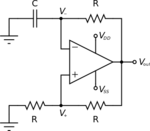
How to build circuit square wave form multi vibrator from 741 ic??
 

As with any other OP respectively comparator https://en.wikipedia.org/wiki/Relaxation_oscillator#Comparator.E2.80.93based_relaxation_oscillator

osc.png

Consider that uA741 has a low slew rate of 0.5 V/µs and can't generate fast square waves.
 
hello,
i have successfully build square waveform

- - - Updated - - -

hello triangular is also generated after integrating a square wave how to get pwm?
 

Attachments

  • square wave.png
    square wave.png
    126 KB · Views: 188

If you take the signal from the cap and buffer it, you get a triangle wave.Now feed that back into another amps positive input, an analog signal into the negative and you'll have PWM.
 
you can also feed some voltage into the v(-) terminal of your circuit (through a resistor) and get some PWM too
 
"Square" would be relative, and a 741's limited slew rate
would limit what frequency you could call it any kind of
"square" at. Worse, when what you want is a narrow
duty cycle at either end of the PWM range. Consider
that a well formed pulse ought to have about as much
"flat top" time as it does rise, fall time and that a PWM
that can't go to 10% or 90% duty is not much of a good
PWM. Your min clean pulse width would be like 3*V/SR
and your max frequency for a good modulation something
like (SR/V)/30.

At 0.5V/uS (DS) and 30V supply (DS) you're talking a
sweet 180uS minimum pulse width (well formed as I
described). Maybe your standards are lower. But below
about 120uS you've got a "runt pulse" and nobody likes
that.

Leaving aside potential ickiness such as, how does the
741's output stage behave (delay, etc.) when you wind
up the amplifier by using it as a comparator.
 
The simulation circuit in post #3 suggests that the original poster isn't stuck to 741...

hello triangular is also generated after integrating a square wave how to get pwm?
You should specify your requirements explicitly. To get a linear and constant frequency PWM, three OPs (or more exactly, one OP and two comparator functions are needed.

An inverting integrator and a comparator with hysteresis form a linear triangle generator, a second comparator compares the triangle with the control voltage to make the pwm signal.

There are other options to make a linear sawtooth or triangle generator if you refer to the complete toolbox of analog circuit design. You can study existing pwm controller ICs to learn about it.
 
how to do speed regulations in it to make constant speed of a motor
 

ok, i was using dc gear motor
ok how to measure rpm which motor to use?
 

Some motors come with a tach output.
What is the need of a constant speed ?. Does the accuracy/repeatably matter? Do you require multiple speeds? If so what kind of dynamic range. Is the motor driving a heavy load?

If this is an old DC motor with brushes, measuring back EMF gives a good measurement of speed.
Harder to do on a PWM drive.

Another point about driving a DC motor with PWM. If you are driving one end of the motor to ground with a transistor (PWM to the base). The reversed diode across the motor is a must. Without the diode the motor looks like a big inductor and you won't get any current through it.
 
Status
Not open for further replies.

Part and Inventory Search

Welcome to EDABoard.com

Sponsor

Back
Top