Continue to Site

Welcome to EDAboard.com

Welcome to our site! EDAboard.com is an international Electronics Discussion Forum focused on EDA software, circuits, schematics, books, theory, papers, asic, pld, 8051, DSP, Network, RF, Analog Design, PCB, Service Manuals... and a whole lot more! To participate you need to register. Registration is free. Click here to register now.

Colpitts Crystal Oscillator Design

Status
Not open for further replies.

thandana

Junior Member level 1
Joined
Nov 27, 2014
Messages
19
Helped
0
Reputation
0
Reaction score
0
Trophy points
1
Activity points
367
Hi All,

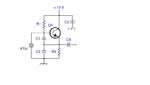
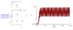
I want to design a colpitts crystal oscillator with operating frequency of 4MHZ. This is the calculations that i have done, please check and advise.

I want to calculate the values of R1, R2, C1, C2, C3 and C4, see attachment.

I have selected C1 = 68pF and C2 = 220pF.

I saw a guide saying C1 should be a value between (39 – 82)pF and C2 between (39 - 220)pF for good performance

Ve = 10% of Vcc
Vcc = 12V
therefore Ve = 10% of 12V
=1.2V

Since Vbe for silicon is approximately 0.6V
Vbe = Ve + Vbe
= 1.2 + 0.6
= 1.8V

Also Ie = Ib + Ic
since Ic > Ib
there Ie = Ic = 1,2mA

Beta = Ic/Ib = (1,2mA/12µA)=100

therefore R2 = Ve/Ie = 1,2/1,2mA = 1K

Rc = 12/1,2mA = 10KΩ

R1 = (Vcc -Vb)/10Ib = (12-1.8)/(10X12µA) = 85KΩ
R2 = Vb/10Ib = 1,8/(10X12µA) = 15KΩ


Please can you check for me if the above calculation is correct, please
 

Attachments

  • Circuit Diagram.png
    Circuit Diagram.png
    23.1 KB · Views: 173

The R1, R2, Rc calculation is obviously for a different circuit, in so far the resistor values are not correct and won't bias the transistor in a useful operation point.
 

@FvM what should the resistors be? Or rather, how should i calculate them? Please share?

@kripacharya, once the resistor are correct would be to try build the citcuit and test using oscilloscope.
 

Knowing the ESR of the crystal is needed to determine the correct bias values since you need to have a gm high enough to overcome the ESR of the crystal when combined with the calculated total Xc to sustain oscillation.
 

Attachments

  • colpitts_xtal.png
    colpitts_xtal.png
    18.4 KB · Views: 122

Hi E-Design,

How do i get the ESR of the crystal?

- - - Updated - - -

@ E-Design, how did you get the values for the circuit? Can you please show me the calculations..
 

In many cases to obtain better a phase noise you prefer to have a bigger bias current. That increases the saturation output power of the oscillator, and hence also the sine signal to oscillator noise source levels. But you should be carefull not to increase it too much because you can overstress the crystal resulting in damage. Check in the datasheet of the crystal what the maximum rated power of power dissipation is.
 

In many cases to obtain better a phase noise you prefer to have a bigger bias current.

This statement is not %100 correct.Because when you increase the bias current, you will increase the noise contributors coming from active device.( especially Shot Noise will be increased rapidly in BJT transistors)
There is an equilibrium point for Phase Noise shifting between bias current and Phase Noise.

I agree with you that the noise power increases, but so does the output power. Typically a noise generaion is proportional with the bias current, but the output power is squared proportional. So in general the oscillators with best phase noise have highest power consumption, because the SNR (look at Leeson's formula) is better. But yes there may be pitfalls, it's just a general rule of thumb.
 

Status
Not open for further replies.

Part and Inventory Search

Welcome to EDABoard.com

Sponsor

Back
Top