Continue to Site

Welcome to EDAboard.com

Welcome to our site! EDAboard.com is an international Electronics Discussion Forum focused on EDA software, circuits, schematics, books, theory, papers, asic, pld, 8051, DSP, Network, RF, Analog Design, PCB, Service Manuals... and a whole lot more! To participate you need to register. Registration is free. Click here to register now.

p channel mosfet for light dimming

Status
Not open for further replies.

svizoman

Junior Member level 3
Joined
Oct 4, 2010
Messages
28
Helped
0
Reputation
0
Reaction score
0
Trophy points
1,281
Activity points
1,577
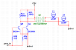
Bellow is my circuit design. I am using dual p channel mosfet (FDS4935BZ) to dimm two H7 bulbs using PIC PWM. Since bulbs are connected to the ground in the headlight itself I can only use P channel mosfet. Since P channel mosfet is on when 0V is on the gate I am also using third P channel mosfet to provide 12V from the car's ignition to the gate of dual channel mosfet that actualy controls the current through two H7 bulbs. So when PWM from the PIC is 0 bulbs shoud be dimmed to 0 and when PWM from PIC is 255 bulbs should shine with full brightnes.

Problem is that none of this worked. Bulbs shined at full brightnes even when PWM was set to 50 (20% duty so should be 1V) and also circuit started to overheat. Strange thing is that third mosfet (ZXMP7A17G) that only controls voltage to gate of dual mosfet got burned out.

schematics.JPG
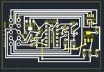
circuit board.JPG

Yellow lines are wire connections on the other side of PCB. All the surface mount ICs yellow markings are shown mirrored since they are fliped over on the other side when soldered!
 

Hi,

to control a FET you don´t speak of absolute gate voltage.
Allways refer the gate voltage to the source voltage. --> Voltage between gate and source --> V_GS

for the high current FETs:
* I recommend to use a resistor beween each gate and source. (instead of your gate circuit)
This ensures, that the FET is OFF by default.

To switch it ON:
use a n-Channel FET or a NPN to drive the gate LOW. (similar to your circuit at RA1)
Use a resistor to limit the the current, but ensure proper V_GS levels.

Mind that a light bulb will draw a multiple of it´s nominal current when cold.
Mind that car voltage may be very dirty .. with much spikes on the lines.
You need to protect your FETs from these spikes.

Klaus
 

So did you have this circuit in mind? 12V to the gate of P MOSFET and NPN draining the gate of mosfet. How will NPN behave with PWM? Will it be proportional to the duty cycle or not.

diagram .JPG
 

001.png

Try this method to drive the p-MOS.
Better to use a feedback system for dimming by using ADC.

- - - Updated - - -

The best way to make a constant current or voltage dimmer is use a LPF to change the PWM into a voltage level than feed into upper circuit at PWM_IN. Use current sense resister for feedback of current and simply potential divider circuit for voltage feedback. Read the current or voltage from ADC and then update the PWM duty cycle.
The constant current LED driver is shown in the figure. You can apply your own changes and make your Lamps glow very preciously. While changing the circuit please take care of power rating. Please revert if you need more help with this topic, covering the power needed and current rating of the lamp needed to dim and also the levels of dimming.001.png
 

Hi,

About your schematic of post#3:
* you need the gate to source resistors (as already recommended)
* you should connect a current limiting resistor at the collector of the bjt (as already recommended)
Now I recognized that you have two individual power sources for the light bulbs...therefore you need to standard signal switching diodes from each gate to the collector-resistor.

Klaus
 

Hi,

* you need the gate to source resistors (as already recommended)

there is one 10k

Hi,

* you should connect a current limiting resistor at the collector of the bjt (as already recommended)

there is one 10k

Hi,
Now I recognized that you have two individual power sources for the light bulbs...therefore you need to standard signal switching diodes from each gate to the collector-resistor.

so what you mean I need two separete NPNs to switch each MOSFET?
 

Hi,

It´s becoming difficult...

FET2.JPG
In the picture you see two red circles. One for gate, one for source. --> I don´t see a resistor between them.
In the picture you see two magenta circles. One for gate, one for source. --> I don´t see a resistor between them.

****
I don´t see a current limiting resistor from collector to gate

****
You don´t need two NPN --> you just need two diodes.

****
see picture
FET3.JPG

Klaus
 

Sorry if I am getting anoying but I really don't understand why I need those resistors?

I thought that 10k resistor that leads 12V to gate of dual MOSFET and to the colector of NPN acts as current limiter for both MOSFET and NPN.
Do I miss something about working of MOSFETS?
Only logic answer to your aditional resistor will be that voltage that goes to MOSFET source can come out also on gate of mosfet and trough NPN and if so I still don't see sense of having voltage from light source lead trough G-S resistors to the gate of mosfet.

I actualy found somewhere else that diagram of NPN controling the voltage on gate of mosfet.

Sorry for my lack of knowledge and thanks for all the help.
 

Hi,

... already written in post#2:

The state of a mosfet with open (floating) gate is unpredictable. It may be conductive, it may be high ohmic and it may be somewhere inbetween.

A Mosfet is high impedance when V_GS = 0. V_GS is the voltage between gate and source.
Therefore (isn´t it obvious?) a resistor exactely between this gate and this source ensures that the Mosfet is OFF by default.
Now you have a known and predictable Mosfet state. in either case... no matter what input signals you have at the sources

Klaus
 

Status
Not open for further replies.

Part and Inventory Search

Welcome to EDABoard.com

Sponsor

Back
Top