Continue to Site

Welcome to EDAboard.com

Welcome to our site! EDAboard.com is an international Electronics Discussion Forum focused on EDA software, circuits, schematics, books, theory, papers, asic, pld, 8051, DSP, Network, RF, Analog Design, PCB, Service Manuals... and a whole lot more! To participate you need to register. Registration is free. Click here to register now.

Flyback PSU - Instability Problem

Status
Not open for further replies.

ElecDesigner

Member level 5
Joined
Jul 22, 2014
Messages
94
Helped
4
Reputation
8
Reaction score
5
Trophy points
1,288
Activity points
2,190
Hi,

I am testing a Flyback convertor that uses the LM5021 IC.

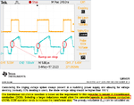
I have an issue where at some load / Vin combinations every other PWM pulse is a different width. I am using the IC variant that allows 50% duty cycle max and as far as I can see , for example, one pulse might be close to 50%, the next 30%, then 50% and so on.

I wouldn't have thought it would be the Voltage feedback loop but I have slugged that anyhow, with no effect. I am not an expert but it sounds like the sort of thing you might get with Duty Cycles above 50% (requiring slope comp to fix it).
As the controller I am using is limiting the Duty cycle to less than 50% I am confused as to why this is happening.
 

Hi,

we have about no chance to help you with the given informations.

We need YOUR schematic with all the voltages and device values and device names.
Also we need an exact description at which situations you see the unstability and at which situation it is stable.
Input voltage, current. Output voltage, current.

Klaus
 

Sorry for the frustration with lack of information.

Regarding schematics - I keep to a minimum for confidentiality reasons.
I was hoping for some generic pointers on the effect rather than something specific.

It seams to be happening at some window where the duty cycle is not near the 50% limit but not narrow either.
The its designed to work at about 170V min, sat at 175Vin the instability happens between 8W and 15W (30W is full load).

I attach a screenshot from the scope. Yellow is Gate Drive, blue is current sense. The current sense has some bias on to keep it running continually at light loads (see datasheet) but removing that has no effect.

View attachment TEK0045.BMP
 

Hi,

from the picture (please in future use the "Insert image" button) it seems..
* the indutor is not saturating (good)
* you have a current mode controller (OK)
* PWM stops at the desired current (good)
* but it starts with different current (why?)
.. I have no clue what may cause this..

Other users may be more familiar with LM5021...

Klaus
 

Check your transformer calculations and design. It looks like it goes into CCM mode. The application note says it should remain discontinuous.
 

Attachments

  • ramp.png
    ramp.png
    41.7 KB · Views: 109

E-Design
Indeed it is operating in CCM (I have thought about doing a DCM version for comparison).
I read that bit in the application note as a choice for that particular design, I don't see that the controller can only operate in DCM.

KlausST
You point about the start current is interesting. Its difficult to determine "cause and effect" here. Where the current ramp starts at a higher value, it is due to the fact that the DC was higher on the previous cycle giving less diode on time (which makes sense).
 

Can you show the current waveform at a duty cycle where you don't have the sub-harmonic switching?

It is difficult to help you if you can't share more details of your actual design unfortunately.
 

Scope Capture.JPG

Doesn't look too much different apart from the obvious.......
 

Without seeing your diagram and layout, I am not sure how we can assist you. It may be a design problem, a layout problem, control loop problem, or a combination with other things.
 

Subharmonic oscillations are a well-known problem of current mode converters operating in CCM with > 50 % duty cycle.

LM5021 has a slope compensation feature to suppress subharmonic oscillations. Did you utilize it in your circuit?
 
  • Like
Reactions: Libin

    Libin

    Points: 2
    Helpful Answer Positive Rating
FvM,

Yes I read about subharmonic oscillations in such circumstances.

I went for the version of the LM5021 that does not allow a duty cycle of greater than 50%, hence it does not have the slope comp feature.

That said, I done some further work with a lower inductance transformer (covering more of the line/load range in DCM mode) as an experiment. The oscillations do appear to be related to CCM mode or the DCM/CCM boundary.
 

Classical subharmonic oscillations shouldn't occur with < 50 % primary duty cycle. But the current waveform in post #3/#5 is somehow unusual. What causes the plateau current?
 

I have attached part of my schematic and part of the 5021 datasheet.

The plateau current is caused by my R33 biasing the current sense signal to prevent skip cycle mode. I have tried removing R33, the waveform changes to have a more classical current sense ramp look about it but the oscillation still occurs.

Capture4.JPGCapture3.JPG
 

Status
Not open for further replies.

Similar threads

Part and Inventory Search

Welcome to EDABoard.com

Sponsor

Back
Top