Continue to Site

Welcome to EDAboard.com

Welcome to our site! EDAboard.com is an international Electronics Discussion Forum focused on EDA software, circuits, schematics, books, theory, papers, asic, pld, 8051, DSP, Network, RF, Analog Design, PCB, Service Manuals... and a whole lot more! To participate you need to register. Registration is free. Click here to register now.

Which is a better way of inputting an FSM

Status
Not open for further replies.

hobbyiclearner

Full Member level 2
Joined
Oct 27, 2014
Messages
142
Helped
2
Reputation
4
Reaction score
2
Trophy points
18
Activity points
1,296
Hi,

I wanted to know which is a better method of inputting FSMs in Xilinx; the manual way or through statecad. I am asking this as I noticed that statecad was discontinued from ISE 11. This made me suspicious as to which is the better way. BTW, is there any statecad equivalent in vivado. Also what is its equivalence in Altera. I basically prefer the graphical way rather than typing out the various cases of the FSM.

Thanks and Regards,
Hobbyiclearner.
 

Make your life easiest by sticking to HDL. Cross platform and no conversion needed for simulation
 
  • Like
Reactions: GihanG

    GihanG

    Points: 2
    Helpful Answer Positive Rating
OK...what did you mean by cross platform pls. And statecad has its own simulator. Isit not reliable?

Hobbyiclearner.
 

Cross platform would mean your HDL will work in any HDL compiler (Altera tools, Xilinx, Synopsys, Cadence etc), and simulate on any HDL simulator.
Statecad will be a Xilinx only tool. Meaning whatever you produce will only compile for Xilinx parts. And like you said, it was discontinued in ISE 11, which was 6 years ago. The last version of ISE was 14.7, so I guess they dont really care about it much.

Write HDL to make your life easiest.
 

I would stick with HDL. Perhaps use an editor that makes some of this easier.
 

Cross platform would mean your HDL will work in any HDL compiler (Altera tools, Xilinx, Synopsys, Cadence etc), and simulate on any HDL simulator.
Statecad will be a Xilinx only tool. Meaning whatever you produce will only compile for Xilinx parts. And like you said, it was discontinued in ISE 11, which was 6 years ago. The last version of ISE was 14.7, so I guess they dont really care about it much.

Write HDL to make your life easiest.

OK.. just to be clear... the FSM drawn in statecad can be used to generate equivalent HDL code (in VHDL or verilog). So implicitly the state diagram becomes compatible with any tool. But yes, Xilinx discontinued statecad in ver 11. So the doubt in my mind. Is there any statecad equivalent in Altera's Quatrus and Xilinx Vivado? That is are other brands supporting it/ is xilinx continuing it in some other form?

Regards,
Hobbyiclearner

- - - Updated - - -

I would stick with HDL. Perhaps use an editor that makes some of this easier.

OK... pls. make a suggestion of an editor which makes it easier.

Thanks,
Hobbyiclearner
 

Some of this is editor customization. At one point, I had vimscripts to take a list of states and generate a enumerated type, state, and a case statement.

Vim and Emacs support syntax-highlighting, block-editing, marker-based code-folding, and are scriptable. Notepad++ and Sublime are also widely used. In this case, block-editing is the key feature, so all four can be useful. (I don't want to start an editor's war here.)
 
If your companies paying, get them to buy sigasi and give us a review :grin:
 

Maybe this is close enough for you. http://qfsm.sourceforge.net/index.html. It's probably one of the few tools like this I've seen outside of one or two very expensive packages, which I can't even seem to find anymore (maybe out of business?).
 
Maybe this is close enough for you. http://qfsm.sourceforge.net/index.html. It's probably one of the few tools like this I've seen outside of one or two very expensive packages, which I can't even seem to find anymore (maybe out of business?).

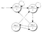
Yes, I was talking of such tools where one can enter the FSM diagrammatically and generate the HDL code. Tried it for a simple 101 detector. FSM.png. The generated code is as below (could not find an icon for ataaching a text file :( )


Code VHDL - [expand]
1
2
3
4
5
6
7
8
9
10
11
12
13
14
15
16
17
18
19
20
21
22
23
24
25
26
27
28
29
30
31
32
33
34
35
36
37
38
39
40
41
42
43
44
45
46
47
48
49
50
51
52
53
54
55
56
57
58
59
60
61
62
63
64
65
66
67
68
69
70
71
72
73
74
75
76
77
78
79
80
81
82
83
84
-- This file was generated by               
-- Qfsm Version 0.54                    
-- (C) Stefan Duffner, Rainer Strobel           
 
-- Inputs:   x
-- State/Output y
-- State_0      0 
-- State_1      0 
-- State_2      0 
-- State_3      1 
 
LIBRARY IEEE;
 
USE IEEE.std_logic_1164.ALL;
 
ENTITY FSM IS
  PORT (clk: IN std_ulogic;
        rst_n: IN std_ulogic;
        x: IN std_ulogic;
        y: OUT std_ulogic;
        debug_state: OUT std_ulogic_vector (1 DOWNTO 0));
END FSM;
 
ARCHITECTURE behave OF FSM IS
 
TYPE state_type IS (State_0, State_1, State_2, State_3);
SIGNAL next_state, current_state : state_type;
 
BEGIN
  state_register: PROCESS (rst_n, clk)
  BEGIN
    IF rst_n='0' THEN
      current_state <= State_0;
    ELSIF rising_edge(clk) THEN
      current_state <= next_state;
    END IF;
  END PROCESS;
 
  next_state_and_output_logic: PROCESS (current_state, x)
    VARIABLE temp_input : std_ulogic_vector(0 DOWNTO 0);
    VARIABLE temp_output : std_ulogic_vector(2 DOWNTO 0);
  BEGIN
    temp_input(0) := x;
    CASE current_state IS
      WHEN State_0 => temp_output := "000";
        CASE temp_input IS
          WHEN "1" =>
            next_state <= State_1;
          WHEN "0" =>
            next_state <= State_0;
          WHEN OTHERS => next_state <= current_state;
        END CASE;
      WHEN State_1 => temp_output := "010";
        CASE temp_input IS
          WHEN "1" =>
            next_state <= State_1;
          WHEN "0" =>
            next_state <= State_2;
          WHEN OTHERS => next_state <= current_state;
        END CASE;
      WHEN State_2 => temp_output := "100";
        CASE temp_input IS
          WHEN "0" =>
            next_state <= State_0;
          WHEN "1" =>
            next_state <= State_3;
          WHEN OTHERS => next_state <= current_state;
        END CASE;
      WHEN State_3 => temp_output := "111";
        CASE temp_input IS
          WHEN "0" =>
            next_state <= State_2;
          WHEN "1" =>
            next_state <= State_1;
          WHEN OTHERS => next_state <= current_state;
        END CASE;
      WHEN OTHERS => temp_output := (OTHERS =>'X');
      next_state <= State_0;
    END CASE;
    y <= temp_output(0);
    debug_state <= temp_output (2 DOWNTO 1);
  END PROCESS;
 
END behave;


So my initial query still remains: Is it advisable to enter an FSM through graphical tools and then generate an HDL file or one should enter the HDL code of the state machine manually. My suspicion can to existence because all such graphic editors ( such as statecad in Xilinx package, QFSM) have gone out of support (ie not developed any further or not provided with any software package).

BTW, I have a few queries from the generated VHDL code.

1. In the entity, what is this 'debug_state' and why is it used?

2.I had chosen a Moore machine. Why am I getting both 'present state' and input 'x' in the process sensitivity list of the VHDL code.

next_state_and_output_logic: PROCESS (current_state, x)

Looking forward to the answers.

Regards,
Hobbyiclearner
 
Last edited by a moderator:

Always go with HDL. It is portable and needs no licence to edit. As you have seen, tools fall in and out of favour/support, and graphical files dont play well with version control, so text based HDL is always the best option.

1. Debug state is just a way to see what state the state machine is in from outside the entity (maybe on hardware)
2. X is present because temp_input(0) is assigned to x. It will need to be updated when x changes. If it was missing, there would be a simulation/hardware missmatch.
 

I have never seen anything like this being used in the industry, the benefit of seeing an FSM is marginal. Good designers have this ingrained in their brains already.

Maybe for some entry level undergrad courses we would use 'diagram drawers'. Go with HDL is the takeaway here.
 

Besides everything TrickyDicky and ThisIsNotSam has said. One big issue with a graphical FSM is you can't diff the FSM without generating the HDL code and then you might have a lot of unexpected differences if the tool does something different with a minor FSM change. With a hand written HDL FSM when it's in source control you can diff the versions and can easily see what changes have been made to the FSM between versions.
 

Status
Not open for further replies.

Part and Inventory Search

Welcome to EDABoard.com

Sponsor

Back
Top